General
From the Stage Lights module, you control the lights (fixtures) on set though the Digital Multiplexer (DMX) protocol or direct video output (video fixtures). You can dynamically set the color, tie the color to a region of a clip playing to a LED volume or serving as a green-screen background, or output (part of) a clip to a series of light (beams) – also referred to as image-based-lighting (IBL).
The Stage Lights module is available with a Live FX and Live FX Studio license. With a license, the Stage Lights module shows as one of the main tabs at the bottom of the screen.

A basic understanding of the DMX protocol is required to operate the module. This guide assumes that you are familiar with the concepts of DMX-universes and -channels as well as some basic network terminology.
Protocols
Communication from Live FX to physical fixtures on-set or virtual fixtures in other software goes either through a form of DMX or direct video output. There are three DMX protocols supported: sACN, Art-Net and USB. Video fixtures either go through the dual head output of Live FX or through a Video IO channel. In the Protocols menu the settings for each of these protocols are managed.
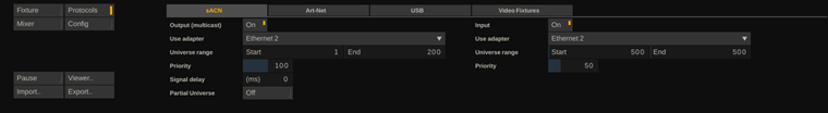
sACN
sACN or Streaming-ACN is the colloquial name for the ANSI E1.31-2016 standard. sACN uses UDP to multicast DMX data over a network. Live FX can both send (output) DMX data through sACN as well as read (input) DMX data through sACN. The latter is used to allow control of certain Live FX functions through a lighting console or other media server. DMX input is discussed in the section on lighting console support, later in this guide.
Output On / Off. Explicitly enable / disable sACN input.
Network Adapter. If your system has multiple network interfaces, please select the network adapter to use to communicate with the fixtures. Note that it is possible to use Wi-Fi, but often a wired connection provides a more responsive setup. Both input and output can use the same network adapter but not necessarily.
Universe Range. For output, the data for all fixtures that are patched to a universe within the range set, is sent over sACN. Note that this might even overlap with the ports set for Art-Net. In that case the data is sent over both protocols. For sACN input the only incoming data patched to a universe within the range is processed. All other incoming data is ignored. Furthermore, the input range should normally not overlap with the sACN output universe range.
Priority. sACN data can be tagged with a priority level (0 – 200 with default 100). For output from sACN, the receiving end determines how to process the priority setting. For incoming sACN data, the priority setting is checked against the priority setting with the universe that came in before. If the priority setting of the new incoming universe packet is higher or the same, the data is processed. If lower, the data is ignored.
Signal Delay (milliseconds). If the sACN output controls fixtures that need to work in sync with e.g., a LED volume, then it sometimes might be needed to delay the sACN signal. There is no automated way to determine the exact delay but one way of determining it is by filming image/color changes on the fixture and the LED volume and with trial and error adjusting the delay till the changes show up on the same moment in the recording.
Partial Universe. The sACN protocol allows to send partial data packages – e.g., when only the first 100 channels of a universe are used, Live FX can send just that part and not extend the send package with 412 empty channels. This limits the load on the network. However, not all receiving software / hardware works correctly with this (e.g., this is not supported by Unreal Engine). By default, Live FX always sends out a full universe.
Art-Net
Art-Net is a public domain network protocol developed by Artistic Licence. It is designed to transport DMX512 and RDM packets over a network. The Art-Net implementation in Live FX is a bit more restrictive than the sACN implementation but is fully functional with a limited set of fixtures. The Art-Net implementation only outputs data, no input for lighting console support. Furthermore, it can output to max 4 universes at any one time.
On / Off. To enable Art-Net is needs to be explicitly switched on.
Adapter. Art-Net uses the selected network adapter to search for other Art-Net nodes in the network. Like sACN, Art-Net can use Wi-Fi but the discovery process for other nodes in general works better in a wired setup. In some cases, the discovery process does not work because of routing problems on the network. In that case, please ensure that the Broadcast Limit (see below) is set to 0.
Active Nodes. When activated, Live FX will scan for Art-Net nodes on the network and list those together with their IP address and supported universes. Live FX can use this information to unicast data to the nodes.
Sub-Net. An Art-Net device can have a specific sub-net set to be used in addressing the device. If you want to address that device, then the Sub-net settings should have the same value. Usually this is 0. The main Net number for the DMX Art-Net module in the software is currently always 0.
Port Universes. The Art-Net implementation has 4 output ports, where each port can address a different universe. You can alter the universe to any value in the 1-16 range.
Broadcast Limit. When set to 0, any DMX data send out is broadcasted into the network. When set to a different value then Live FX will first check which of the detected Art-Net nodes requires data of a specific universe and if this number is below the limit set, the data is unicasted. This saves on network resources but depends on the proper functioning of the detection process.
USB
Live FX will automatically scan for USB-DMX devices and list all devices found with their name and serial number. With each device you can specify a universe by clicking in the universe column. You can enter a number between 1-16 and the DMX data of any fixture that is patched to that universe is sent through the device.
Video Fixtures
Video Fixtures are not controlled through one of the DMX protocols but are more like LED tiles in an LED wall (with a certain pixel resolution) and as such connected to an LED wall processor. Live FX outputs to an LED wall processor as a normal display device: either though the Dual Head display or a Video IO output (SDI or NDI). The image flow is displayed in the diagram below.
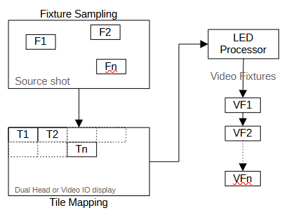
In Stage Lights you define one or more tiles (T). The tiles are linked to a fixture (F) which sample a certain region of the source shot - not sampling it down to a single color but maintaining the full sample region. The tiles are mapped onto a display output (Dual Head or Video IO). The complete image is sent to the LED Processor, which has the same tile-mapping as in Stage Lights and passes the sampled image region to the correct physical video fixture (VF). Note that the tile mapping in Stage Lights should exactly match that in the LED processor. The sampled image region does not have to be the same size of the linked tile though. If the size differs, the sample region is scaled into the tile region. This might affect the aspect of the sample.
The Video Fixture tab in the Protocols menu has all the tools to create tiles, map the tiles and link them to a fixture.
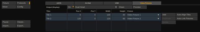
On / Off. To use Video Fixtures, you explicitly enable the protocol.
Display. Select the display to use to output the tiled images.
Tiles. The list of Tiles displays the name-label, position, and size of each created tile. Click inside the position of the size column to update the values.
The X/Y position represents the left upper corner of a tile in the selected display. Note that the tile position and size is independent of any scaling that was set on the image in the Monitor settings.
In the last column, called "Fixture", you select the fixture to link to the tile. The sample region of the fixture is then drawn into the tile region of the display output. When selecting a fixture, the fixture type is changed to Video Fixture (see also the next paragraph on the Fixture menu).
Add. Create a new tile.
Duplicate. Add a copy of the selected tile.
Delete. Remove the selected tile.
Auto Align Tiles. Automatically align all tiles next to each other from top left to right bottom, per row. This leaves the size of the tiles as is and just updates the X and Y position based on the sizes.
Auto Link Fixtures. The automatically creates a new fixture for each tile that is not yet linked to a fixture. It also adjusts the sample region of all linked fixtures to the size of the tile.
Clean. By default, the output to the selected display for the Video Fixtures will contain the main image that is currently playing. All tiles are drawn over that image. This way, the LED processor might still be able to use part of the source image for output to a LED wall. Only the part with the tiles drawn over is then used to send to the physical fixtures. When Clean is enabled, the main image is no longer drawn on the output and all tiles are drawn on a black background.
Preview. This option opens the dual view in the Viewport with on the right side the same view as is being output to the selected video fixture display. In case the dual head only is sent to an LED processor, which only has the fixtures connected, it is hard to see what the full output looks like. Do note that the dual view has the same resolution as the main view in the Viewport, which might differ from the resolution of the selected video fixture output. In that case, the full output might not show or be partly dimmed because of the Guide settings of the display (see Player – Settings – Guide menu).
Fixtures
Fixtures are maintained in the Fixture list, which is available by swiping to the left side of the screen or by enabling the Fixtures button in the top menu bar. From the Fixture List panel you create, delete, and select fixtures. The properties of the (first) selected Fixture are exposed in the Fixture menu spread over different tabs:
- Fixture Patching – set the DMX universe and channel layout.
- Color Sampling – set the color sampling region or the fixed color for the fixture.
- Grading and Animation – adjust the sample color with a series of grading tools and animate the grade and/or DMX channel values.
- Color Transform – apply a (custom) color space transform to the sample color to match with the fixture’s color space. Optionally scale or clip the sample color between a custom minimum and maximum.
The last three tabs reflect the color pipeline for fixtures before the color values are converted to DMX values.
Fixture List
In the Fixture list panel, among other things, you create new fixtures, label fixtures, (multi)select fixtures, remove fixtures and (un)group fixtures. You open the Fixture list by selecting the corresponding button in the top menu bar or by swiping the pen to the left side of the Viewport.
The list is by default docked to the left side of the Viewport. You can move the list by dragging the gripper button in the lower right corner of the panel. By dragging it back to the left side of the Viewport it will automatically dock itself again.
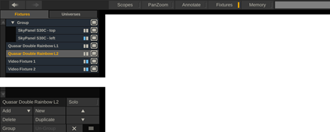
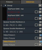
The Fixture List has 3 parts: Fixtures tab, Universes tab and the command buttons at the bottom.
Fixtures tab
All fixtures are listed with their name and a barcode behind it which indicates:
- Is the fixture using a Fixed Color rather than sampling the color of the current clip playing.
-
Is the fixture a Video Fixture rather than a traditional DMX fixture.
Next to the barcode is the active-toggle button. Clicking this, toggles the fixture active / non-active.
When fixtures are grouped together, the group item can be collapsed / expanded with the button in front of it. Collapsed groups will remain functioning normally.
To multi-select fixture items, either:
- Ctrl + Click fixture items to add them to the selection (or remove them from the selection when already selected)
-
Shift + Click to select all fixtures in between the prior selected fixture and the new selected fixture.
Multi-select is useful for grouping items or updating the properties of multiple fixtures at once, both are discussed in more detail later in this guide.
You can also drag / drop fixtures from one position to another in the list. Select a fixture and hold down the mouse button momentarily to attached it to the pen. Drop the fixture at another location in the list by clicking on that location. When you Alt + Click a fixture and hold down the pen, you are making a copy of the fixture, which can then be dropped elsewhere in the list.
Universes tab
In the universes tab, each fixture is displayed with its DMX universe and channel mapping. If there are fixtures patched to the same universe + channel address, then the fixture is displayed in red. If there is any overlap detected, the Universes-tab itself will also show in red.
Deactivated fixtures are not included in the check. Video Fixtures are also not included as they are not patched to a universe.
Left of the (de)active toggle button is a Solo toggle button for the fixture. The toggles the solo-tag of a fixture. In the next paragraph the Solo mode is discussed in detail and how it relates to the fixture solo toggle.
Fixture List Controls
Just below the list area of the Fixture List panel is the text-slate to update the Name of all the selected fixtures.
The Solo (mode) button when enabled, does two things. It switches to Solo mode and tags all selected fixtures as Solo. When in Solo mode, fixtures that are tagged as solo are sent normal color data. All other fixtures are sent ‘black’ color data – switching them ‘off’. When switching off Color mode, the solo tags with the fixtures remain active. But when next time activating Solo mode, the tags of all fixtures but the selected ones are removed. While in Solo mode, you can update the tags of individual fixtures through the Fixture list (Universes tab) to add / remove fixtures from the solo selection.
With the Add option you can load a new (DMX) fixture from a template or a new video fixture. Loading a fixture from a template means that all dmx channels are already defined and the fixture is ready for usage. In the next paragraph loading a template is explained in more detail.
The New option creates a new fixture with standard 10 channels but no predefined channel layout and applications. You will need to setup the channel layout yourself in the Fixture Patching tab.
The Delete option removes all selected fixtures. This is a confirm button, which requires you to click the option a second time confirm the delete action.
The Duplicate option creates a copy of the current selected fixtures and adds them to the end of the list.
To Group fixtures together has several advantages. You can toggle them on/off with a single click. By just selecting the group item you can re-position the color sample region of all underlying fixtures at once or update a channel property for all underlying fixtures at once. You can group fixtures by selecting multiple fixtures and clicking the Group button. You can add fixtures to an existing group by drag / dropping them in the group. To remove a group, select the group item and click the Ungroup button. Note that the sample region position of all fixtures is maintained, including the group-offset. Grouping can also be a temporary thing to quickly update multiple fixtures and then revert back to a straight listing.
The Arrow buttons are used to move the fixture selection up or down. More importantly, these buttons are mappable and controllable from a (grading) panel/console.
The Cross button closes the Fixture List panel and with the Gripper section next to it, you can re-position the panel by dragging it.
Add Fixture from Template
The Add button in the Fixture List or in the Fixture menu, allows you to load a fixture template, either from:
Open Fixture Library
When selecting the Add - > Open Fixture Library the first time, the software will attempt to download a complete library of available fixture templates to your local computer (c:\programData\assimilator\dmx\ folder). After the download it will show a panel from where you select a manufacturer, the fixture type and the mode it should operate in. This will then determine the DMX channel layout for the fixture. Click Ok to add the selected fixture to your setup.
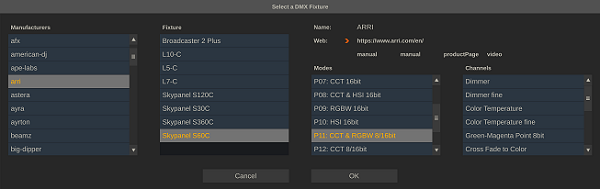
Note that the fixture list does not contain all fixtures from all manufacturers around the world. Neither are the templates guaranteed to be perfect. Manufacturers decide themselves to be included in the library and the library is open for others to upload a template. The list that the software downloads to the local drive is not automatically updated. At some point you might just delete the dmx folder from your disk to force the software to download a new version.
GDTF templates
After selecting the Add - > GDTF Template option, a file browser panel opens and you select the actual .gdtf template from disk. Next, you select one of the available profiles in the template, in the profile list panel.
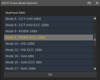
The selected profile should be the same as the profile that is set on the physical fixture. After clicking Ok, the fixture is created including the channel layout, channel types and possible channel linkage.
Note that in most cases, the fixture profile is interpreted correctly but, given the vast number of different types of fixtures, there might be cases where certain features are not implemented or different than some fixtures expect. If you encounter templates that do not give the correct results, please contact support.
Single and multi-select fixtures
Before discussing the various functions in the Fixture menu, it first needs to be clear how the selection in the fixture list affects the display and changes of fixture properties.
- Single fixture. Properties of the selected fixture are shown in the Fixture menu. Changing a property only affects that fixture.
- Single Group. The sample region properties of the group are shown and can be updated. All other properties show the values of the first fixture in the group. Updating any of those properties, update the properties of all the fixtures in the group.
- Multiple Fixtures. The values of the last selected fixture in the multi-select are shown. Changing a property, changes it for all fixtures in the selection. Changing the size or position of the sample regions, updates all fixtures by the delta of that change, not to the absolute values.
- Multiple Groups. Only the sample region position, and size are shown and can be updated. The properties of the last selected group are shown, while any update is applied to all the selected groups - as the delta of the change, not as absolute values.
- Groups and Fixtures simultaneously. No properties are shown or can be updated.
Fixture Patching
In the Fixture Patching tab of the Fixture menu, you patch a fixture to a specific universe and channel address and specify the channel layout of the fixture in case of a DMX fixture. None of this applies to video fixtures. When you enable the Video Fixture option, all other options are greyed out.
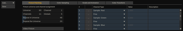
Patch the fixture to a specific address using the Universe and Channel control at the top of the menu. The Universe number determines which protocol(s) are used to send it out. The Channel number is between 1 and 512. Note that the Universes tab of the Fixture List will show you when fixtures are patched to the same / overlapping address ranges.
The Channels control specifies how many DMX channels the fixture uses in total.
Some fixtures – like e.g. light beams – contain multiple sub-fixtures. With the Repeat in Universe, you specify how many times to repeat the channel layout. In case of a light-beam consisting of e.g. 24 individual LED lights, each using 6 DMX channels, the Channels counter would indicate 6 while the Repeat in Universe would indicate 24.
The Globals control is only available for fixtures with multiple sub-fixtures. The Globals-setting indicates how many of the DMX channels of a fixture are only sent once – after all the repetitions. In case of a 6-channel light beam with 24 LED lights, specifying 11 channels with 5 globals – the first 6 channels are repeated 24 times, and the 5 global channels are added at the end – specifying a total of 24 x 6 + 5 = 149 channels.
With the Repeat the Universe setting you duplicate the specified fixture in subsequent universes. To follow the above example. If you have a total of 16 of the light-beams (mounted together), then you do not have to specify them each separately but can just set the Repeat the Universe to 16. If the first beam was set to Universe 24, the next 15 beams use universe 24 - 40. This functionality is particularly useful with the sACN protocol that multi-casts the DMX data based on universe number.
Channel List
The Channels setting specifies the number of the channels of a fixture. In the Channel list the column type / function is specified. In case a template was used to load the fixture, the channels have all been defined. In some cases, you might have to manually specify the function of each channel.
The first column of the list contains the channel number. In case the channel is a global channel (see the Flabel setting above), the channel number has a ‘G’ post-fix.
The second column contains a button to open the Channel Editor panel, discussed in more detail below. The third column specifies the channel type. The following channel types are possible.
- DMX Value. The channel can contain any integer value between 0 and 255.
- DMX Custom Range. The channel can contain any value between a custom set range (using the Channel Editor). This value is underneath translated to the 0-255 range when sending the DMX data.
- DMX Option List. The channel value can be selected from a list. Each of the list items is associated with a DMX value between 0-255.
- DMX Fine. Certain properties of a fixture need a more fine-grained value range than the 0-255 (i.e. 8 bit) for a DMX channel. By setting a channel type to Fine, the channel value is tied to the prior channel which together now can span a range of 0-65536 (i.e. 16 bit).
- Control Dimmer. This ties the channel value to the fixture dimmer control on the Grade and Animation tab of the Fixture menu.
- Sample Red, Green, Blue. Use the fixture sampled color or fixed color. Take the value of the red, green, or blue color channel.
- Sample Luminance. Use the fixture sampled color or fixed color. Calculate the luminance value of the 3 channels combined.
- Sample Hue, Saturation, Brightness. Use the fixture sampled color or fixed color. Calculate the Hue, saturation, or Brightness value of that.
- Sample Color X, Y, Z. Use the fixture sampled color and the current clip colorspace. Transform the color to XYZ.
- Sample Color Cie x, Cie y, Cie Brightness. Use the fixture sampled color and the current clip colorspace. Calculate the xy and brightness values.
- Sample CCT. Use the fixture sampled color and the current clip colorspace. Calculate the CCT value in Kelvin.
- Link OSC. Use the Open Sound Control Live Link input, based on the OSC tag that is entered in the Description column of the Channel list. Note that in the Channel Editor you can still set a custom range for the OSC value. If you do not, then the value is interpreted as a standard 0-255 DMX value. Any value outside that range is truncated.
- Link Universe Channel. The sACN protocol allows to also capture incoming DMX data. Using this channel type, you can use / forward the incoming data to a specific fixture. In the Description column you specify which universe / channel to use by entering just two numbers, optionally pre-fixed as e.g. “U12 C67”.
- Control Animate 1 – 6. This allows you to link the channel value to one of the six possible animation channels with a fixture. The animation values are managed from the Grade and Animation tab in the Fixture menu. Animations are discussed later in this chapter.
- Template: Custom. You can create your own custom ranges and options lists and save them as templates. You can then assign such template as the channel type. Creating channel type templates is discussed with the Channel Editor, below.
The Value column shows the selected or calculated value for the channel. You can either manually enter a value here within the range or list that is set for the channel, or the calculated / derived value for the channel is shown but you cannot change it. Note that if you want to see the actual DMX value that is being sent to the fixture, you need to open the DMX Raw Viewer – discussed later in this guide.
In the Description column you can enter a descriptive name or description for the channel. This label is also used in the Mixer menu and the remote control web interface. Note that with channels that are linked to OSC Live Link data or captured DMX data, the description column should reflect the link to the data as discussed above.
Channel Settings Panel
Clicking the button in the second column of the Channel List opens the Channel Editor panel. In this panel you can customize the channel type and function, as well as create channel function templates.
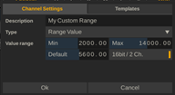
The Description field corresponds with the Description column in the Channel List and is a descriptive label for the channel. Except for OSC / DMX Linked channels, where the description contains the OSC tag or the DMX universe/channel address.
With the Type dropdown you set the main channel type.
- With a Range Value, you enter Minimum / Maximum values and the Default value for the range. Enable the 16bit / 2 Ch. option to indicate that the value is to be stored in 2 DMX channels, meaning that the channel should be followed by a channel of type Fine.
-
With an Option List, you enter a series of key / value pairs as a comma separated list. The values are DMX (0-255) values. Example: “Option A, 10, Option B, 125, Option C 250”. The Default value for the channel corresponds to the index of the name/value pair in the list starting at 0/. So, for the example a default of “1” corresponds to “Option B”.
-
The DMX Value type presumes a value between 0 and 255. The Default value with this type should also lie in this range.
-
With the Sample / Control / Link channel type, select one of the predefined channels.
The fixture is only updated after the Ok button is clicked. Clicking outside the panel or on the Cancel button, just closes the panel without updating the fixture.
In the Templates tab of the panel, you can create a template of the channel type by entering a template name and clicking the Add button. A template channel type can be selected directly in the Channel List dropdown and saves time setting up your fixture. Using a template name that already exists, will overwrite the existing template. Click the Apply button to update the selected channel to the selected template. Use the Delete button to remove the selected template from the template list. Note that any fixture channels that were created with the template will not be affected when removing or overwriting a template.
Color Sampling
In the Color Sampling tab of the Fixture menu the sample color for the fixture is determined: either a fixed color or a sampled color of a specific part of the current clip that is playing. The color sampling is the first part of the fixture color pipeline (coinciding with the tabs in the Fixture menu): Sampling => Grade => Color (space) Transform => DMX value.
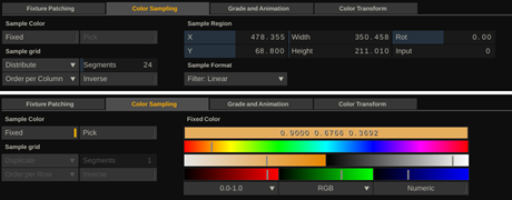
Enable the Fixed option to select a single color for the fixture. When enabled the color selection controls appear. With those you can adjust hue, individual RGB channels, saturation, and luminance to set the desired color. When you enable the Pick option, you can click anywhere in the Viewport image to directly select a color. Note that the Fixed color can also be animated, using an animation channel for each of the RGB values separately.
By default, the color for the fixture is taken from the sample region in the current selected clip. The Sample Region is set through the X, Y, Width, Height, and Rotate controls or by using the overlay control for the selected fixture in the Viewport. The X and Y origin is the centre of the clip. The Rotate setting is in degrees.
Use the Input control to set which input node of the current (composition) clip to use for sampling the color. E.g. when using a Switcher node with multiple channels – setting Input to 2, indicates to always use the second channel/input of the Switch node for sampling. When leaving it to 0, the color sampling is done from the active channel of the Switcher node.
The Filter option determines how the sample color is derived from the sample area. With a Linear filter, the sample color is the average of the 4 centre pixels of the sample region. The other filters, like e.g. Lanczos, use the full sample region to average. These so-called higher order filters give a better representation of the sample area but are also more expensive in terms of computing power required. In case of a high number of fixtures, using these types of filters might affect playback performance. The linear filter might result in more volatile results from one frame to the next, but it has a much smaller impact on playback performance.
Sample Grid
If a fixture consists of multiple sub-fixtures, the sample region can also be split up into a grid, where the individual cells are tied to the sub-fixture. The Distribute, Segments, Order and Inverse controls are used to map the cells. These controls are only enabled when one or both of the Repeat options on the Fixture Patching tab is enabled.
Either you Duplicate the sample color to all sub-fixtures, or you switch to Distribute mode to split the sample region up into individual cells. By default, the sample region is split up into a single row of cells. The figure below shows how to use the Segments, Invert and Order controls to adjust the mapping of the cells to the sub-fixtures.
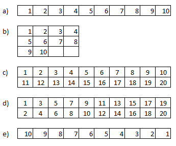
Figure a) shows the default distribution of the sample area when using a repetition of 10. By using the Segments control you can adjust the number of rows that are using in the sampling area. In figure b) Segments is set to 3 and generates a pattern of 3 rows and 4 columns - leaving 2 samples unused.
In some fixtures the repeated lights are not following a row-after-row pattern (figure c) but the lights are ordered per column (figure d). In that case you can use the Order dropdown to specify a column-order rather than a row-order. This also works if the fixture contains more than 2 rows of lights.
Finally, you can invert the order of sampling - figure e) - by using the corresponding option.
Note that neither the Sample Grid options, nor the Filter option is available for Video Fixtures as for these fixtures no sampling or averaging is done.
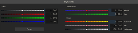
Grade and Animate
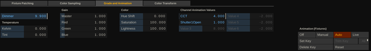
The Dimmer control on the Grade tab in the Fixture menu is only available when one of the DMX channels of the selected fixtures is patched to the Control: Dimmer function, in the Channel List.
The Temperature controls (Kelvin, Tint), the Gain controls (master, red, green, blue), as well as the Color (Hue-shift, Saturation and Lightness), are all applied to the sample color after the (down-scale) filter. The Temperature controls are similar as the Kelvin/Tint controls int he Numeric menu for shot-grading. The Kelvin value is an offset to a default temperature value of 5600 kelvin. Note that in most cases the temperature of the source shot is unknown. Also note that this value is not related, nor affects a possible CCT DMX-channel of a fixture.
All the grade controls and the dimmer control can be animated. This is (obviously) also true for the generic animation controls. The controls are only available when a DMX channel is patched to one of the 'Control Animate' options in the Channel List.
Animation
Animations for fixture parameters work the same way as animations for grading and compositing of clips. The full explanation of how animations work, how to work with the animation editor, how to navigate key frames, is available in the other part of the user guide for the software (Chapter 7, paragraph 12 and 13). Just to highlight a few important aspects:
- The generic animation controls are available in the right bottom corner. Start animation by selecting the Manual or Auto option.
-
With the Auto option enabled, any change to a control value results in a new key frame. With the Manual option enabled, Use the Set Key to create a new key frame with the current control values.
-
Alternatively, use the quick-keys associated with animations, described in the help-panel that you pop-up by pressing the ‘h’ key.
-
Switch to key-frame animation by clicking the ‘S’ button on the main toolbar, left of the playback controls.
-
Open the animation editor with a specific animation channel by clicking the Animation button on the main toolbar, holding down the mouse button and drag the cursor to the control, of which you want to open the animation curve. The cursor will change color when a control has an underlying animation.
The following properties of a fixture are animatable: sample region X, Y, Width, Height, Rotate, Fixed Color (red/green/blue), Dimmer, Gain (master/red/green/blue), HSL controls (hue/saturation/lightness), Generic Animation controls (6).
Color Transform
The third tab in the fixture menu contains the option to adjust the colorspace or EOTF of the sample color, as well as limit the color range.
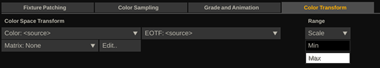
The color space and transfer function of the sampled color is that of the clip it is sampled from (as set in the Live FX tab, Media menu for the clip). Use the Color space and EOTF dropdowns in the Color Transform tab to transform the sampled color to the desired target color space and EOTF. Leaving both controls to <Source> leaves the sample color as-is.
In case you need a non-standard (color space) transform, you can enter a 3x3 matrix to be applied to the sample color. Click the Edit button to open the Matrix panel to enter the numbers of the matrix and add a tag to it or select an earlier entered matrix from the Matrix dropdown.
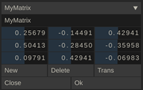
In the Matrix Edit panel you enter a new matrix or update a previously saved one. Click New to clear the controls to enter a new matrix. When clicking Ok without entering a Name tag, the matrix is stored with the fixture but not included in the matrix list. When entering a Name tag that is already in use with another matrix, that latter matrix is overwritten with the new one. Use Delete to remove a matrix from the matrix list. Note that changing a previously saved matrix or deleting it, will not affect fixtures that use this matrix: when selecting a matrix with a fixture, a copy is made of that matrix. When clicking Cancel, the selected fixture is not updated, but any new matrices or changes to matrices in the list are maintained.
The Trans button transposes the matrix. The matrix is multiplied with the (RGB) sample color as-is. If you e.g. need the matrix to be applied on pure linear color data, then use the color space and EOTF controls to first convert the sample color to XYZ / Scene Linear.
Use the Range option to limit the sample color between a minimum and maximum. There are two ways to apply the range min/max:
- Clip – if the color value of the sample color is below the minimum or above the maximum, the color is just set to the respective minimum or maximum.
-
Scale – the sample color is adjusted from a 0 – 1 range to the min – max range.
Mixer Menu
The mixer menu provides an alternative way for managing fixtures. Rather than having to select a fixture in the Fixture List to adjust its settings, the Mixer Menu provides a standard set of controls for all fixtures next to each other. Next to the standard controls with each fixture, you can open a grade- or detail-settings panel, specific to the fixture.
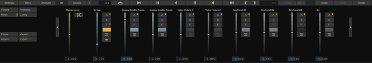
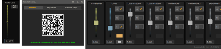
If fixtures have been grouped together, the Mixer menu will show a group item for all underlying fixtures. You can navigate into a group by using the folder-button. You can navigate back up a level by selecting the Arrow up button next to the Master slider.
When there are more fixtures than fit on the screen, scroll buttons will appear left and right of the Mixer menu. Alternatively, you can pan the menu by using <space> + click/drag or scroll the menu left/right by using the mouse wheel. In addition, you can also extend the height of the menu by dragging the Gripper control in between the Animate and Source buttons on the main menu bar, up or down.
The Master Level applies to all fixtures. By default, this is set to 1 and as such does not have any effect on any fixture. When set to any other value the master level affects fixtures in one of two ways:
- If a fixture has an explicit Dimmer channel, the value for that channel is multiplied with the Master Level.
-
If a fixture does not have a Dimmer channel, then the Master Level is applied on top of the Master Gain setting, which affects the sample or fixed color.
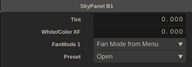
Each fixture (and group) has a series of standard controls in the Fixture menu.
The main Level slider works similar as the Master Level but only for the individual fixture, or for all the fixtures in the group. Note that the Level sliders for group-items are displayed in blue.
The A button toggles the fixture Active / not active. The S button switches the fixture to Solo mode. For more information on the Solo mode, see the section in the Fixture List paragraph above. The F button toggles the fixture between Fixed color and Sample color. Toggling the button for a group toggles the mode for all underlying fixtures.
When in Fixed color mode, the color button below the F button shows the selected color. Clicking the color button opens the color selector to adjust the color selection. When in sampling mode, the color button shows the current sampling color – based on the sampling region. Clicking the color button opens the Grade panel with the Temperature, Gain and Color controls.
The bottom button for fixtures opens the Details Setting panel for the fixture with all adjustable channel settings. The specific set of controls depends on the channel layout of the fixture. For a group-item, the panel shows the controls that apply to the first fixture in the group. Adjusting the settings will affect all fixtures in the group (if applicable to the fixture).
The Mixer menu is also available through the built in web server. That way you can tweak the fixture settings from a mobile device while walking around on-set. Open this interface by clicking the QR-code button next to the Master Level slider. This pops-up the Remote Control panel with a QR-code that you can scan from your mobile device to connect to the local web server.You can also click the URL below the QR code to open the web interface in the web browser of your local machine.
Keep the following aspects in mind:
- To connect to the web server, the device needs to be on the same (Wi-Fi) network as Live FX is. Live FX should not be blocked by any firewall on the system or on the network.
-
The remote interface does not automatically update when you change the fixture in Live FX itself: E.g. adding / removing fixtures, adjusting the channel layout of a fixture. When using the remote interface, use only that. If you do change the setup in Live FX, then ensure to refresh the web page on the remote device.
Config Menu
The config menu harbours settings that define the behaviour of the Stage Lights module.
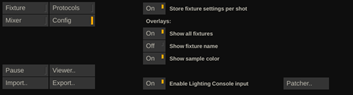
Store fixture settings per shot. The base fixture setup is stored as a project setting: all fixtures and their channel layout / types. Fixture settings like position / size of the sample region, grading and the actual channel value can also be stored per shot. That way you can easily create a different look / feel for different scenes. Switch to a different shot or create a version of the current shot (see version stack) and adjust the fixture setting for the scene. Do note that - as mentioned – when e.g. removing a fixture, you are removing it for all shots / scenes in your project.
Overlay settings. The overlays show the sample region / sample matrix with a fixture. There are three overlay settings:
- Show overlays for all or for just the selected fixture. When dealing with a high number of fixtures, showing an overlay for each all the time can become a bit messy. Showing the basic overlay has some but relatively little impact on performance.
-
Show the name of the fixture with the overlay. The name makes it easy to identify a sample region but might make the view messy with a high number of fixtures. The same as for the overlay itself – showing the name has some but relatively little impact on performance.
-
Show the sample color. This option toggles showing the actual filtered and graded sample color inside the overlay. This is useful visual feedback, but keep in mind that when showing the sample color for all fixtures this might have a relatively high impact on playback performance. When playback performance is already pushed to the limit (high resolution media / complex composition / effects), then showing the overlays with the sample color might tip impact over the edge to lose real-time playback. In that case, consider switching this setting off or switch showing all overlays off.
Lighting Consoles
As discussed in the section about the sACN Protocol, Live FX can also capture incoming DMX data. Primarily this is intended to capture data from a lighting console. To use a lighting console with Stage Lights, these steps are required:
- Enable sACN Input in the Protocols menu and set the universe range to cover the range that the console uses.
-
Switch on the Enable Lighting Console setting in the Config menu.
-
Patch the functions available for Lighting Console control to the universe / channels that the console is using, using the DMX Lighting Console Patching panel.
-
Patch the Stage Lights functions on the Lighting Console using a template, either supplied by the console manufacturer or by using the .gdtf template, or by manually patching the console using the DMX tables. Open this link to download the correct version: DMX Tables and Profiles.
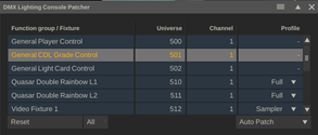
- Patching is done on the console as was as in the Stage Lights module. First you decide which Live FX / Stage Lights functions you want to patch to the console. There are 4 categories:
-
General Player Control. Control Play mode (Play / Pause / Goto / etc.), Select active version, Apply memory or gallery grade on current shot.
-
General CDL Grade Control. Grade the current image based on Color Decision List parameters: Offset, Power, Slope, Saturation.
-
General Light Card. From the Quick Link dropdown in the Live FX menu in the Color FX tab you can create Light Cards: coloured layers that are included on an LED volume projection to use a part of the LED wall as extra light source. The Light Card function group allows you to control the position, shape, and color of the light card from the console.
-
Individual Fixture Control. Next to application-level function groups, you can also patch functions of individual fixtures. Two profiles were created for this.
-
Full. Control all aspects of a fixture – sample region positions and size, fixed color value, color grade (gains, HSL), color clip / scale range. Use this profile if the (physical) fixture is fully defined in Stage Lights and all you need is to control the levels from a console.
-
Sampler. Control just the color sampling region position and grade. This profile can be used to just do color sampling by Live FX in a basic virtual fixture and let the console use the output of that fixture to combine it with the output to the actual physical fixtures.
To patch one or all of the function groups, you specify which universe and channel start number to use in the patching panel. When patching an individual fixture, you also select which profile to use.
Use Reset to clear the patch from the selected item(s). Or enable the All button to clear all items in the list. Note, that you can select multiple items by holding down the Ctrl key and clicking additional items. The Auto Patch button will look at the first item in the list or selection and then start patching the next items by incrementing the universe number and re-using the channel number.
Other Stage Lights Functions
The Pause button, when enabled, suspends sending out DMX data to any fixture. The Pause state is maintained in the project settings – meaning that when Stage Lights is paused and you exit the project and enter again at a later moment, it will revert to the paused mode.
The Viewer button opens the Raw DMX Viewer panel. This panel shows the actual DMX values that are being sent out or that are being captured. At the top of the panel, you set the universe that you want to view.
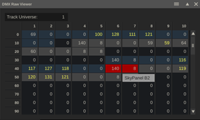
Below that it shows the values of the 512 channels in the universe. If a fixture is patched to channels in the selected universe the channel backgrounds are coloured and the tooltip with the channel will tell the name of the fixture. If multiple fixtures are patched to the same channel, the channels show a red background.
Note that the channel values only update every second – if the value changed, it shows up highlighted in yellow. The actual DMX data is sent out at the frequency (frame rate) of the clip that is playing. The update frequency of the Raw Viewer is lower so that the DMX values remain human readable.
The Import / Export functions allow you to save the complete setup (.admx) or the settings of an individual fixture (.fdmx) to file on disk or load a previously saved file into your project. This way you can quickly replicate a setup from one project to the other.
Stage Lights Workflows
The functionality of the Stage Lights module in Live FX is applicable in a wide range of workflows. Here are some suggestions / topics to consider.
No Stage Lights
Not using Stage Lights. There are plenty of situations when using Live FX where Stage Lights is not needed and / or all light management is done from another system. In that case you can consider enabling the Advanced System Setting "Hide the Stage Lights module", to keep the UI as clean as possible.
Single System
Use Stage Lights in combination with LED volume projection or live green screen compositing, from a single system. Stage Lights can sample in real-time and in-sync from the projection/background clip and control the on-set fixtures to set the correct ambient light and reflections on the talent and foreground.
Multiple Systems
Even though Live FX can very well control both the LED volume and Stage Lights from a single system from a performance point of view, the number of operator tasks might become too high for a single operator. Having multiple operators on a single system does not work well. Also, in some cases you might require a different general grade on the shot for the projection than for the color sampling for the fixtures. In that case it might be opportune to move the Stage Lights function to a separate system. There are different ways of ensuring that both systems remain in sync.
Capture Live Feed
If the timing between background and light control allows for a little slack (a few frames), then consider having he primary Live FX system send out an SDI or NDI feed (or split off the signal to the LED volume) and let the Stage Light system capture that feed. All color sampling can be done from that feed. As said – sending / capturing a live feed will add a number of frames latency and as such the action on the fixtures.
Sync Player
An alternative is to ensure that the media for the LED volume / green screen background is on both systems – possibly using a proxy version on the Stage Lights system. Then use the Sync Player function to keep playback of both systems in sync at all times. In general, the Live FX projection system would serve as master. The Sync Player function is available from the Tools dropdown in the top menu bar of the player.
In cases where you are using many different background-shots / doing multiple scenes – it might be easier to switch the Play-mode of Live FX to ‘Timeline’. That way all shots are in the player and the master / client does not have to switch back and forth between construct and player.
Integrate with other Systems
The Stage Lights module can of course also be used without the projection / greenscreen functionality but in combination with other systems: e.g. in an Unreal Engine nDisplay LED volume workflow or serve purely as color sampler for a lighting console that controls all on-set fixtures.
Just as with using multiple systems, if Live FX can capture any live / derived feed (SDI/NDI) from the main media being projected, it can grade and color sample from it to drive the stage lights. In its most basic form, it just opens a rendered version of the projected media, and the Stage Lights operator syncs playback.
Setting up color sampling from a captured feed of rendered media only takes a few clicks. Next you can setup a number of virtual fixtures with just RGB DMX channels that sample from the media. A Lighting Console can pick up the DMX data and consolidate it with the actual physical fixtures that are patched in the console. The console can directly control the sample region on the media by patching the console in the Stage lights module (see the paragraph on Lighting Consoles, earlier in this guide).