General
The Calibrate function in Live FX (available as of v9.7 build 1153) uses the OpenVPCal application to create a calibration LUT for LED wall output for a specific camera. OpenVPCal stands for Open Source In-Camera Visual Effects Calibration Framework. The framework aims to reduce metameric failure and LED panel technology limitations that cause the colors that are sent to an LED Wall to not be the same color that is recorded by the camera. OpenVPCal is an initiative of Netflix and Ocra Studios.
Live FX simplifies the calibration process of OpenVPCal by combining the playback of the by OpenVPCal generated color patches directly to the LED wall, by live capturing the input of the camera pointed at that LED wall and then in one go to pass the captures to OpenVPCal for processing and creating the resulting calibration LUTs. Live FX then applies the LUT as a display LUT with the selected monitor output.
The OpenVPCal software and documentation is available from here https://github.com/Netflix/OpenVPCal.
The Calibration function is available from the Construct menu in Live FX, using the Calibrate button.
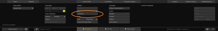
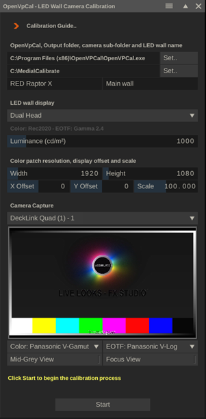
This opens the OpenVPCal LED Wall Camera Calibration panel where you configure the various settings of the calibration.
Calibration Steps
OpenVPCal Executable and Output settings
The first step is to ensure that the OpenVPCal application is installed correctly and that the reference to the executable in the Live FX calibration panel is correct. If you did not install OpenVPCal or did not install it in its default location the reference to the executable is displayed in red. Use the Set button to point to the installed OpenVPCal.exe application.
The output is the root folder where the calibration function stores the generated color patches, the captured camera input as well as the resulting LUTs and OpenVPCal specific project files.
Use the Camera sub-folder label to create a sub-folder within the root folder for the specific camera that you are calibrating. The LED wall name is used in the file naming of the resulting LUTs. When no name is entered a default tag is used.
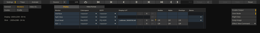
LED Wall display
Select the display output that is connected to the LED wall that you want to calibrate. This can either be the dual-head or a Video IO output. Below the display drop down, the colorspace and EOTF of the selected display are shown as they have been set in the Player–Settings–Monitor menu.
OpenVPCall deals with a limited set of display colorspaces and EOTF combinations: REC2020, REC709, ACES, and ST 2084 (PQ), Gamma 2.2, 2.4 or 2.6. If the LED wall processor expects / uses a different colorspace and EOTF then the calibration will not produce correct results.
Set the maximum Luminance of the LED wall in nits (cm/m2). Also ensure that the LED Wall processor is outputting at this maximum luminance and not limiting the signal.
Patch resolution and Display offsets
For the calibration a series of (EXR) color patch images are generated to be displayed and captured. The resolution of these patches should be such that they can be displayed without (too much) scaling and fit within the frustum of the camera. By default, the resolution is set to the size of the selected display, with a default maximum of UHD (3840x2160).
After the patches are generated (first step of the calibration), the calibration panel is opened in the player to display the patches. Optionally use the Offset and Scale controls to ensure that the color patch is displayed at the center of the LED wall and fits on the wall as well as into the frustum of the camera that captures the patch.
The Offset and Scale controls are also used in case an Nvidia mosaic output to multiple LED walls is used. In that case the patches do not need the full resolution of the selected (mosaic) display, but just relate to the wall that is being calibrated. The Offset controls are used to center the color patch on the center of the wall that is calibrated.
The Offset and Scale controls are actually shortcuts to the corresponding controls in the Player–Settings–Monitor menu, in the Formats tab. Any setting you do during the calibration is reverted after exiting the calibration.
Camera Capture
Select the Video IO input channel for the live camera capture. This should show the live image in the panel. If you have not configured a Video IO input, then exit the project and open the Video IO settings panel from the startup screen. Note that in the Video IO panel, you set which YUV -> RGB matrix to use for an SDI device: either a video- or full range matrix. Different cameras require different settings when outputting a log-signal that is captured in Live FX. For most common cameras this is the matrix that should be used:
- Video range (rec709): ARRI, Canon, RED
- Full range (rec709): Sony, Panasonic
If you have a different camera then check the documentation with that camera to make sure what matrix to use when capturing the signal.
With the camera capture signal selection you should see a preview in the Calibration panel. Next, set the Colorspace and EOTF of that camera capture in the drop downs below the preview.
The Mid-Grey View and Focus View are explained later.
Start
Pressing Start will set the calibration process in motion. The OpenVPCal application is opened in the background and the color patches used for the calibration are generated. Next, Live FX opens the Player and shows the first of the color patches – which is the informative patch with instructions on setting up the camera. You should see this image in both the viewport (which is being sent out to the LED wall) as well as in the camera view section in the calibration panel (the readback of that patch through the camera).
Camera Settings
The first color patch contains several grey patches: a color ramp from 0nits to 10,000 nits (max PQ), in steps of 1,000 nits. Use this grey ramp to check that all patches above the max-luminance that was set for the LED wall indeed appear full white (as they are clipped).
The 18% grey frame should also be interpreted as such by the camera. Most cameras have a false-color tool to check the brightness of the captured image. Alternatively, you can use the Middle-Grey View option in the calibration panel. This function displays the live camera capture in 3 colors based on the brightness: grey when plus/minus half a stop from the middle grey value, green when below and yellow when above.
The 18% middle-grey brightness value differs per camera. The Live FX Middle-Grey View uses the EOTF that was set for the live camera signal and the Stops to IRE Conversion for Camera Log Curves as published by Nick Shaw of Antler Post for Convergent Design. The table below comes from this publication about generic false color display.
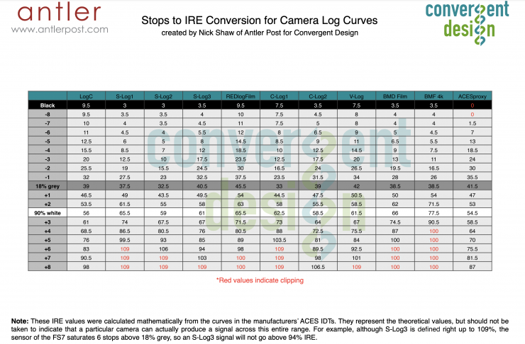
When you use an EOTF that is not included in this table, then the image is first converted to ACES Proxy before calculating the view.
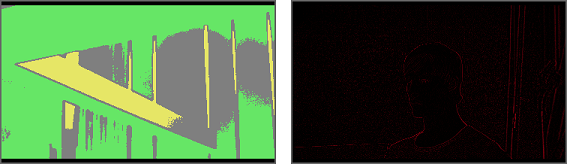
In the calibration panel you also find a Focus View that uses an edge detect function to display the focus object (see right image above). In general, the focus object will not be the LED wall, but rather the actors in front of it. It is recommended to use the same focus of the camera for the calibration as is used for the actual recording.
Start Capture
After the camera has been set up correctly, hit the Start Capture button to start the playback and capturing of the color patches. This might take a bit of time. The panel displays a counter on how many patches there are still to go.
Once the last color patch has been captured, Live FX passes all the rendered and captured frames to the OpenVPCal application in the background to do the actual calibration.
Apply
When the calibration is done, you can directly apply the resulting calibration LUT as a display LUT on the selected display output. You can also manually apply the LUT at a later moment in the Player–Settings–Monitor menu.
After applying the LUT you can toggle the LUT on/off to see its effect.
Results
The calibration process generates various elements and results. The list below show the various elements in the [Main Output]/[Camera]/ - folder:
- project_settings.json. The OpenVPCal application project file. After a calibration in Live FX you can open this file in the OpenVPCal application directly to view the calibration and all the parameters that were used. In fact, you can even redo the calibration based on different settings if needed.
- /capture/. This folder contains all the camera captured color patches.
- /export/calibration/. This folder contains the resulting LUTs and Open Color IO (OCIO) files from the calibration. Live FX uses the .cube LUT file as its display LUT. Note that the LUT files have the LED wall – name as prefix in their name. Furthermore, you can use the 3D LUT or the OCIO configuration file with other software. The resulting 3D LUT presumes the input to be- as well as outputs the colorspace / EOTF that was set for the selected display output (see above). In general this will likely be REC2020 / PQ.
- /export/patches/. This folder contains all the generated color patches that are used to display on the LED wall. Note that the patches are rendered with the resolution of the selected display.
- /results/. OpenVPCal specific files with the results of the calibration.