General
At the heart of LED Volume projection in Live FX Studio lies the Stage Manager. The Stage Manager is where you create a model of your stage with the position and shape of the LED wall(s). This information is used, together with the camera position, to determine the correct image to be sent to each wall. In the Stage Manager you also determine how each LED wall is mapped onto any display output. The Stage Manager can be opened from the Projection Setup panel in the Construct (see below), from the Live FX menu in the Player, or through the right-click popup menu in the Player.
The functions of the Stage Manager are spread over 4 separate tabs.
- Stage – create and manage multiple stage configurations, set the active configuration, export and import configurations, manage and consolidate LED wall meshes, manage general settings.
- Walls – create and manage LED walls in the current active stage configuration. Set wall resolution, tile layout, position and size.
- Mapper – Create mappings on how content for all LED walls in the current configuration should be output over the available display outputs.
- Previs – Add actors / props into the stage configuration to create an overview or camera preview of the scene and take snapshots of that to prep for the actual production.
On the Stage, Walls and Previs tabs, the right side of the Stage Manager shows the stage model. You can rotate (drag), move forward/backward/scale (ctrl+drag / mousewheel) or pan (shift+drag) the model view. Press the Reset button in the lower right corner to revert to the default view. Press the dropdown in the upper right corner to toggle between views:
- View Model. Show the 3D stage model.
- View Camera. Show the stage through the defined camera.
Toggle view options on/off:
- Clip View. Show the media content on the walls.
- Projection Geometry. Show geometry used with planar, spherical or cylindrical projection.
- Camera Frustum. Show the camera and frustum outline.
- Stage Origin. Show the stage origin point to view the relative position of wall(s) and camera. The origin or the stage is represented by the coloured cube/arrows: Z-axis in blue, X-axis in red, Y-axis in green. The origin of the stage usually corresponds to the origin of your (camera) tracking system.
- Floor Grid. Show the floor gridlines.
- Actors. Show any actors as defined in the Previs tab.
Stage
You can maintain multiple stage configurations. Use the Add button to create a new configuration or use the Duplicate option to make a copy of the selected configuration to create a variation. The Delete option will permanently remove the configuration, there is no undo option for it.
Active Stage
Although you can maintain multiple stage configurations, there is only one active at any one time. The title bar of the Stage Manager panel states which stage is active. Select the Active button to make the currently selected stage active. The button will light up green.
When you change the active stage, all projection nodes in the current project, who are usually tied to a specific wall in the stage, are signaled and will attempt to relink with a wall with the same name in new activated stage. If there is no wall with the same name, the node will no longer be linked to a wall and when opening that node in the player, will show a blue frame and needs to be manually linked again. Note that you can safely temporarily switch stages, all existing nodes will automatically link back to the original wall reference when reverting to the original stage.
Import / Export
The stage configurations are stored in the stage_configurations_v2.xml file in the settings folder. All wall-meshes are stored in their own .obj file. The stage configurations are as such system-settings and not stored per project. Also, when upgrading from a pre v9.9 version, the stage_configurations.xml is automatically upgraded to _v2. Note though, that this upgrade only happens once – when temporarily reverting to an older version and then back to the new version, any changes made will not automatically upgrade, unless the _v2 file was explicitly deleted.
Use the Import and Export options to easily transfer a single or all stage configurations between systems. Toggle the All button on/off to export all configurations or just the current selected (not necessarily the active). By default, an exported Live FX stage file (.lfxs) will include all meshes of the walls in the single file. When importing the file, all inline meshes are written to separate files.
The Config button opens a panel with stage manager settings and a Consolidate action.
- Stage Model Folder. The folder where new LED wall meshes are stored.
- When loading an LED wall from an existing mesh file, you have the option to make a local copy or to maintain a reference to the source file.
- Consolidate. This action will make a local copy of all LED wall mesh files into the Stage Model folder, and it will remove mesh files from that folder when they are no longer used in any of the stage configurations. When managing many different stage configurations, the number of meshes increases over time. Since a mesh file can be made externally and have quite a lot of energy put into it to create, the software does not delete those, even if the LED wall was removed from the configuration. The Consolidate is a cleanup tool but note that there is no undo for it.
- By default, an exported stage file includes the mesh data. You can however also opt to include only file-references.
- Set the default resolution for snapshots made from the Previs tab (see below)
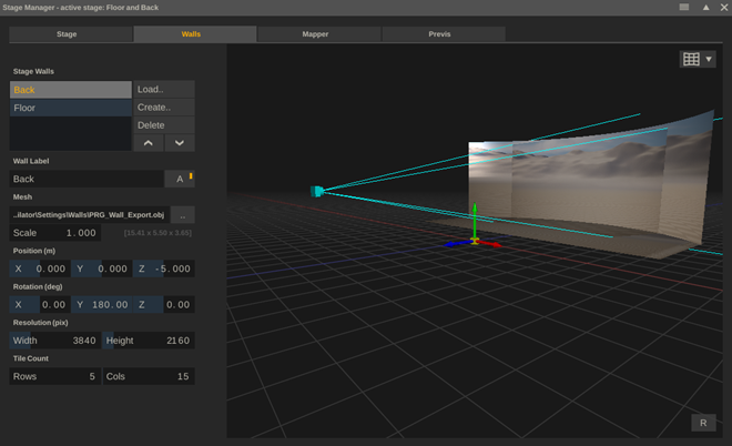
Walls
Each stage contains one or more LED wall definitions / models. To input the shape and size of an LED Wall, you use an .obj file. You can create and save 3D models in an .obj file in a variety of other software and use the Load option in the Stage Manager to load it in. Alternatively, use the Create button to open the LED Wall Model Creator panel.
Model Creator
In this panel you can define the size and shape of a panel, save an .obj file to the selected output folder and add it to the stage configuration directly.
The specifications of the LED wall are defined by entering the number of LED tiles used and the size and resolution of an individual tile. Optionally you can set a curvature per tile, or for the entire wall in degrees. Note that if you enter the curvature, the label at the bottom will show the ‘depth’ of the wall, which is the distance from sides of the wall to the centre-back. Use this if the curvature in degrees is not known and you are able to measure the distance.
There are three types of walls you can create: a standard vertical wall or a floor- or roof wall. The floor and roof walls are rotated and respond to the curvature setting by removing whole tiles from their back side to generate a saw-tooth shape.
When you press Ok, the new wall is added to the stage.
Manage Walls
The Delete button removes the wall from the stage but does not delete the underlying .obj file. Note that this action does not have an undo.
Changing the order of the walls in the list of LED wall can sometimes come in handy, because the order will also be used when creating projection compositions.
When you change the label / name of a LED wall in the active(!) stage, all projection nodes in the current project, that reference this wall, will maintain that reference normally. Projection node in a different project, will however not update and might have lost their reference to this LED wall, the next time that project is started. You might have to manually adjust the wall reference.
Next to setting a name for an LED wall, you can also toggle it active/inactive. Inactive walls are not included in a projection setup.
You can update the reference to the underlying mesh by selecting a different .obj file.
The Scale option can be used with .obj files that have been specified in another dimension than meters. Next to the Scale control, the (physical) size of the wall is displayed (height x width x depth) in meters.
The position of the wall is the offset from the origin of the stage which is usually the origin of your (camera) tracking system. Both the position and rotation are relative to the origin of the wall model, which is usually in the centre bottom/back, but this might be different for externally created models.
The wall resolution is specified as the total number of pixels over the full width and height of the wall (not per tile as in the Model Creator discussed above). This resolution is used for linking a wall to a physical output.
Finally, the wall tile count is only used for generating a preview image to verify the wall mapping (see below). In case of a curved floor/roof wall, this is the count without any curvature as if it is square.
Mapper
In a lot of cases the resolution of an LED wall differs from the standard display output to an LED processor, and a mapping is needed to define how the pixels for the LED wall(s) are output over one or more display outputs. This is done in the Mapper tab of the Stage Manager. In a mapping you define which (portion of a) wall is to be output to which (portion of a) display output.
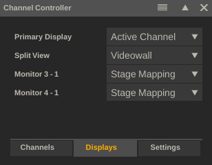
The mappings are then used by a Switcher node to render the correct output image. To ensure that the Switcher renders the correct output, the Channel Controller also needs the correct settings. If a display output is included in the mapping, then it should be set in the Channel Controller’s Display tab to use the Stage Mapping.
A quick recap of the image pipeline:
- A projection setup consists of 1 or more projection nodes (usually one for each LED wall).
- Each projection node is tied to an LED wall in the Stage Manager and as such knows the resolution to output.
- All projection nodes in the setup feed into a single Switcher node.
- The Switcher node uses the settings in the Channel Controller to determine what to output for each display output. In case a display output is set to use the Stage Mapping, it will use the mappings that are associated to the display to create the correct output.
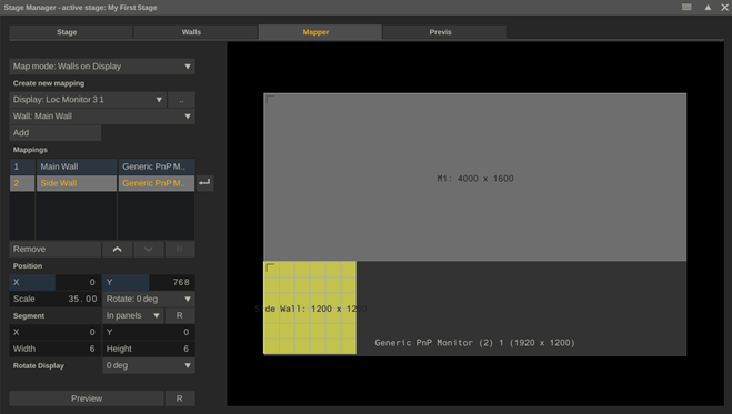
Map Mode
The first dropdown in the Mapper tab determines how mappings a shown in the mapping view on the right side of the panel.
- Walls on Display. Show the selected display as background and show all mapped walls on top of it.
- Displays on Walls. Show the selected wall as background and show all mapped displays on top of it.
Note that this is just a view setting, it does not change anything to the mappings created. In cases where the resolution of the wall is bigger than a single display, then it makes more sense to show Displays on (single) Wall.
Mapping
The Display dropdown shows all display outputs:
- online displays – active GPU, SDI or NDI outputs.
- offline displays – displays that are used in one or more mappings but currently not active / available. E.g. if a display is currently not switched on it will show up as offline – disabled. The stage mapping will remain intact even if a single display is temporarily not available.
- virtual displays – Using the button next to the Display dropdown opens a panel to define a virtual display which can be used in the mapping setup. By creating virtual displays, you can create the full set of stage mappings on any system – even if that does not have any reference displays connected. A virtual display can at any time easily be replaced with a reference to an actual display (see below).
Press the Add button with a display and wall selected, to add a new mapping entry into the mapping list.
The Remove button removes the selected mapping. The Arrow buttons change the order of the mappings, which can make a difference when mappings overlap.
When detecting that an online display has a different resolution from when it was first mapped, the display is shown in red as a warning. To reset the display to use the current resolution, press the R button.
With the arrow button to the right of the mapping list, you can change the display with the selected mapping. When e.g. the display is offline or a virtual display, you can quickly switch to an online display.
Map Position and Segment
The position of a mapping has its origin in the top left corner. You can adjust the position of a mapping either by setting the XY controls or by click+drag the mapping in the mapping view. The Scale option is a percentage. The rotation is for rotating the mapping in steps of 90 degrees. When rotated, the origin point of the mapping will rotate as well in the mapper view.
The Segment options are only available with the Walls on Display view mode. In that mode you can select a portion of the wall to be mapped. You can define a segment in pixels or in (LED) tiles. When using tiles, then dragging the wall (segment) will also snap based on the tile positions. When using ctrl+drag the area select tool is active to select the segment. Click the Reset button to clear the segment and select the full wall.
When setting a rotation for a display, this then applies to all mappings in which the display is used. This option is most useful when mapping multiple display outputs in portrait onto a wide wall.
Preview
The Preview option in the Mapper tab creates a Switcher node with underlying a node that generates a test pattern: a rectangle for each LED wall tile with the row/col number. The preview is meant to make sure all pixels are included in the mapping setup.
When the Preview is invoked from the Construct, the test pattern is automatically opened in the player. When already in the player, the test pattern replaces the active node. Clicking the Reset button reverts to the Construct or prior node/projection setup.
Previs
The Previs tab allows you to add actors to the stage to previsualise a scene – both to view the stage layout as well as by using the camera view of the Stage Manager to get a snapshot of the scene as to show how the real camera will capture it.
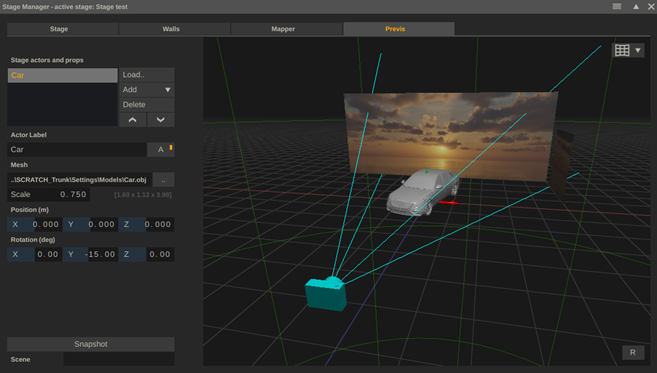
Note that currently the rendering of the actors is relatively limited in that you can only load an .obj or .usd file of which only the geometry is used, no texturing.
Make sure you have the Actors-view option enabled in the model view dropdown (top right corner button).
Adding and positioning actors is similar to adding and positioning walls. You can load an external model or you can select one of the models included with the installation: car, person, basic cube.
The Snapshot button in the lower left corner of the Previs tab creates a snapshot image of the current view. The image is stored in the snapshot folder as set in the System Settings. When creating the snapshot, it is also automatically loaded into the snapshot project tray as well as being attached to the cursor, from where it can be dropped e.g. as version.
Optionally you can set Scene-metadata with the snapshot in the text slate below the Snapshot button.