General
Live FX offers a toolset for virtual production in its broadest sense: live on-set compositing, pre-visualization, and LED wall projection. It includes media- and version management, metadata handling and recording options and as such allows you to both easily prepare live setups in advance as well as create relevant input for post-production. It also integrates image-based lightning (IBL) through DMX allowing you full control over the look and feel of a scene. Here are some examples of supported setups and workflows:
- Basic green-screen setup with 2D or 2.5D (equirectangular) background, using camera tracker to position the background image.
- Green screen with active camera tracking and 3D backgrounds coming from Unreal, Unity, Notch, or internal USD renderer.
- LED wall projection of 2D, 2.5D or 3D media on any LED wall configuration: single wall, multiple walls, curved walls. In a colour-managed context and can graded with the full set of grading controls.
- A pure keyer solution for other applications – using all layering-, masking- and plug-in tools available and send the result as separate RGB and Alpha Video IO channels or NDI.
- Image Based Lighting (IBL) – easy setup of fixture configuration, sampling colour managed image and sending over ArtNet or sACN.
- Record live composites on-set for instant review without the need for offloading cards from the camera(s). Capture all camera tracking and other dynamic metadata in a sidecar file for post-production/VFX usage.
- Animate the virtual camera and use the Unreal or Unity plug-in to directly control the camera in the renderer, capture the rendered output directly from the GPU without delay for your composite, grade and (optionally) record the result.
Live FX exposes live camera tracking, live-links and other dynamic metadata in a way that allow compositors, VFX specialists and DITs to work with it in a familiar creative context rather than in a programming style environment.
Live FX is an application within the Assimilate Product Suite installer and can be combined with other Assimilate product licenses.
This part of the user guide covers the Live FX specific functions and tools. General functions of the Assimilate Product Suite, such as creating a new project, playback-features or grading tools are covered in the generic section / chapters of the product suite user guide. It is recommended to also read that manual or view the various available tutorial videos.
Note that Live FX comes in two flavours: Live FX Studio and Live FX. Certain functions are only available in Live FX studio. In that case the manual will state ‘FX Studio’ only.
Live FX tabs
When you open a project in Live FX, you will find 2 tabs at the bottom of the screen that represent the main modules in Live FX.

- Construct: manage media and preparation of live compositions.
- Live FX: play-back, projection, grading and composition tools.
Left of the tabs is the Toolset dropdown. Depending on your license you will various other toolsets there. To be able to follow this manual, ensure that the Live FX toolset is selected.
Construct tab
Most of the functions and workings of the Construct module are described in the generic user guide. On the main toolbar, there are three important options.

- Import Clips. Load a single shot or a range of clips at once from disk. The options for this are fully documented in the Product Suite guide.
- Live Setup. Quick and easy create a live composite with foreground, background, camera tracker, keyer and more. This function is explained later in this manual, after some basic elements and tools for live compositing have been explained.
- Projection Setup. Quick and easy create a composition shot for projection on LED Wall(s), optionally included with a camera capture and Set extension display. This function is explained later in this manual, after some basic elements and tools for projection have been explained.
In the Construct bottom menu, there are several Live FX specific options.
Switcher node. When you select one or more clip items in the construct you can wrap them together in a so called Switcher node. A Switcher node can playback multiple nodes to different outputs at the same time. The details of the Switcher node are explained in more detail later in the manual.
Calibration. This will start a calibration session for your LED wall to generate a display LUT based to compensate for any color shifts of the recording camera. This function is still a work in progress and not available on all versions yet.
Online Composition. This function allows you to easily switch from a live composition with live input, to an offline composition with recorded proxy media to an online composition that uses the high-resolution camera recordings. This function has its own section later in this manual.
Render. Live FX does not have an elaborate render pipeline like the some of the other toolsets have, as it is focussed on Live capture and projection, for which is has recording capabilities. Sometimes it might be useful though to render a composition node to a single file. The Render panel allows you to render a single clip or a selection of clips to ProRes, H264 or HECV.
Live FX - tab
If you are familiar with any of the other Assimilate Product Suite applications, you will recognize the generic Player layout in the Live FX tab, including the color grading and composite tools. The Live FX toolset has a series of additional functions as well as changes the behavior of the Player in several aspects.
- Playback is always started automatically and in loop mode.
- No timeline playback, by default only single (live) shot playback. If you require timeline playback, then enable the 'Live FX Timeline' option in the User Preferences panel (use the gear-icon in bottom right corner).
- More prominent display of playback / pause (highlight in yellow) to warn that the image showing is not live.
- When entering the Player with a live composite, the Record options are available.
- When adding a fill/matte on a layer, the playback mode is automatically set to loop (rather than once).
Most of the Live FX specific functions in the Player are in or can be accessed from the Live FX menu.
Live FX Menu - Setup
Live Links
Live Links opens the live links panel to manage Live Link sources that captures and sends out camera tracking and other dynamic metadata, which can be used in your composition setup. Live Links are discussed in more detail later.
Stage Manager
Open the Stage Manager panel where you manage the LED wall setup. The Stage Manager is discussed in more detail later.
Calibration
Open the Camera Calibration panel. This panel can also be opened from the Camera menu and in discussed in more detail in the section about the (virtual) camera.
Scene-Take
Open the Scene-Take panel to adjust the scene / take metadata for the current shot. The scene / take metadata is included with any recording you make.
DMX
The DMX button opens the DMX Light Control panel for on-set image based light control (IBL). These functions are discussed later in this guide.
Performance Monitor
Toggle the Performance Monitor displayed centre-top in the View Port on/off to check the playback performance and real time abilities of the system. The Performance display is explained in more detail in the generic part of the manual.
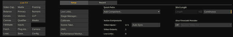
Quick Paths
The Quick Paths drop down is a quick way to add specific functions to your composite. A quick path automatically adds layers, plug-ins, and live link animations to create the desired function. A Quick Path can be undone with a single undo.
Active Components
This section shows you how many Video IO streams are currently active and being used in the current composite, how many Video IO outputs are active, and the number of Live Links are active in the system. This can give you an indication how resources are being used on the system and give possible suggestions what to adjust if playback is no longer real-time. Every input and output stream requires system resources - even if an input stream is not used in the current composite shot that is playing.
Auto Sync
This is a shortcut to toggle the auto-sync option with each input channel on/off rather than having to navigate to each live capture node and toggle the setting on/off one by one. The Auto-Sync option with input channels allows you to automatically synchronize incoming frames from different feeds based on the associated timecode. See for a more elaborate description of this mechanism in the section about capture nodes.
Note that if the current composite contains (multiple) capture nodes with the Auto Sync option enabled while at the same time there are active input feeds with the option enabled but that are not used in the composite - a warning exclamation character is shown. Since all feeds will sync with each other even if not used - the not-used feed might influence the timing of the active shot. It is then better to toggle the Auto Sync option off and back on again. When switching the Auto Sync on from this menu - only the channels that are being used in the active composite shot are in fact enabled.
Shot Length
In most cases the length of a live composite is of less interest as it will playback in a loop and as such always provides a continuous live image. If you however combine the live composite with pre-recorded media or add fixed time animations then the length of the composite – and as such the repeat time – is of importance. When enabling the Continuous option, the mini-timeline for scrubbing the play position is no longer visible. You can only set the continuous mode for live capture nodes. For media nodes, you can adjust the in- and out-point of the clip.
Timecode Provider
Certain composition shots might not have a timecode of their own. E.g. when the composition starts with an empty color frame and the live camera capture is added as a layer on top of that. You can assign a timecode provider to such a shot. Note that this only applies to live composite shots (containing a live element), not to regular media clips. These you can just assign a timecode if needed.
As timecode provider you can either select the system time or you can select one of the available VideoIO input device/channels. Note that if needed, you can select a different channel that is being used in the composition shot.
Live FX Menu - Record options
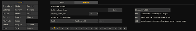
When a live capture node / shot is active in the player, the main toolbar will show a record button. In the record tab inside the Live FX menu you can set the recording options: the Output folder and file naming mask as well as the format and whether to record alpha- and certain audio channels.
Live FX allows to record in one of three formats: ProRes, H264 or DNx. Depending on the selected format additional options become available like ProRes sub-codec, H264 quality or DNx bit rate control.
ProRes 4444 and 4444 XQ also allow to record the created alpha channel of the composite along with the video.
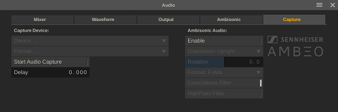
At the bottom of the menu you can enable one or more audio channels to record. In Live FX you can capture the audio with the video input or select a separate audio input through the Audio Panel (Capture tab), which is available from the top menu. Optionally you can delay the audio to sync with the captured video.
In addition to the recording format and audio there are several options on what should be recorded.
Full Shot versus Source Capture. The first option records a single clip with all the sources and grades baked in. The second option records each live capture node in the composition in a separate output, without any grade applied. These source shots are used to create an offline version of the live composition when loaded back into the project. In a later stage you can use these offline compositions to create the online composition with the actual camera raw media. The workflow to create offline and online composites is discussed later in this guide.
Write Dynamic Metadata to a sidecar file. All dynamic metadata and live link data, whether actively used in the composite or not, is written to a comma separated (.csv) sidecar file. The file has the same name as the recorded media file and contains the per frame timecodes so you can link any metadata to a specific recorded frame (see below on how to use the metadata from the sidecar file).
Auto Load the recorded clip. This option loads the recorded clip as version shot into the same slot as the composite shot when the recording is ended. As such, the clip is immediately available for review from the version stack in the player.
Auto Increment the Scene-Take number of the current (live) shot after recording ends.
Metadata Sidecar
The metadata sidecar file that can be created with a recording contains comma separated value (csv) data. You can load and use this data for your online composite with the camera raw media through the Animation editor.
If you e.g. want to use the metadata for the virtual camera of a shot, then first enable manual animation in the camera menu and then open the Animation menu. Select the channels you want to animate and then use the Import button to open the csv file. The software will automatically recognize the sidecar file and open the channel mapping dialog to link the metadata to a specific animation channel.
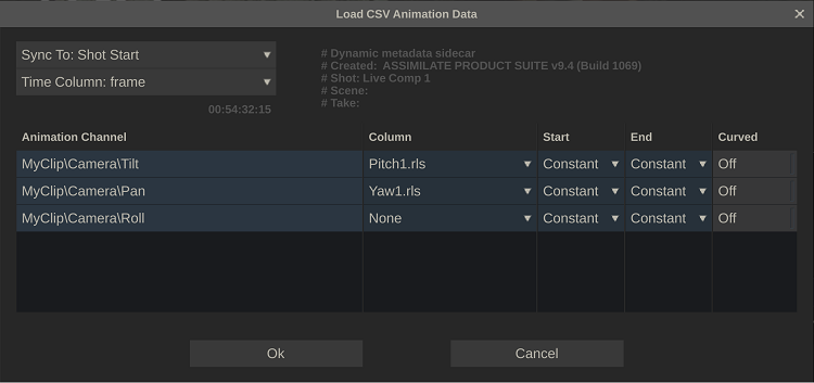
The Sync drop down tells the software from where to apply the animation data:
- Start at the first frame (in-point) of the shot.
- Use the current play-position as the start.
- Start the animation by syncing the shot timecode and the timecode column in the csv. This requires that the csv has a timecode column and that you selected that column from the second drop down.
Next, select with each animation channel the csv column you want to load, using the drop down in the second column. Use the options in the Start and End column to determine the shape of the animation curve at the start and end frame. The last option determines if the each of the animation point is interpreted as part of a curve or connected linearly.
Player Controls
When a live capture node or a composition node that contains a live capture node is active in the player, then the main menu bar will contain Record controls and the Cue Up control.


Auto / Rec
The Auto option is only available in Live FX and when the software is able to recognize and read the record state of a camera from the SDI signal. When the Auto option is enabled, recording will automatically start when the camera starts recording. Alternatively, when the Auto option is off or disabled you can click the Rec button at any time to start / stop recording.
Note that you can also use the Remote-Control function keys to start/stop recording. The Remote Control is available from the Tools drop down menu in the top toolbar in the Player.
Cue Up
Clicking the Cue Up button will ensure that any fill shots (e.g. used as a background in a green-screen context) and/or frame animations are reset to their start position.
Live Links
Live Links are at the heart of compositing in Live FX. They are a source of dynamic metadata that can be used as parameters for composite elements. Live link metadata can also be stored alongside the recording so that it can be used for creating animations in a post-production context.
There are 3 types of Live Links:
- Global sources. Global live links are tied to an external to the software source. This can be a specific camera tracking system or a data coming from other software through the Open sound Control (OSC) protocol. These types of Live Links need to be explicitly activated but are then available in any composite node and at any level. Global Live Links are managed from the Live Links panel that is opened from the Live FX menu or the Tools dropdown in the top menu bar.
- Outgoing. Some Live Links send out metadata for other applications to use. E.g. The Unreal Engine (UE) Live Link sends out the current (virtual) camera metadata over the network to an Live FX Unreal plug-in that controls the camera inside the UE scene it is used in. That way you can generate (and potentially capture) as if it was made with the Live FX virtual camera.
- Sources linked to a specific node. Examples are metadata produced by a Live Tracker plug-in node that is placed on a (live capture) clip to track a specific element, or the Focal Length dynamic metadata that comes with a live SDI capture of a camera. In these cases, the live link data is only available in the composite, at every (sub) node that is on the same level or downstream from the live link source.
Live Links Manager
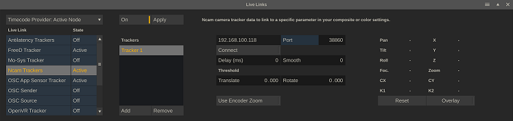
The left of the Live Links panel lists all available live links and their state: active / inactive. To activate or to deactivate a Live Link, select it in the list and click the On/Off button with the Live Link.
All incoming Live Link data is tied to a timecode. Normally that is the timecode of the current (composition) shot that is playing. But just like you could set an alternative Timecode Provider for a composition shot (see earlier in the manual), you can also set an alternative timecode source for live link data. In some case you might use a shot that uses more than one live capture, but you need camera tracking data be tied to a specific capture. Note that this is a global setting. If you set a timecode provider then this is also used by default with any next composition that you open. Of course, you can change the setting at any time.
Live Links – Camera Trackers
Live FX comes with a range of supported camera tracker that you can use. All trackers are presented and controlled in a similar way and have a number of common functions.
Tracker Common
Apply
When a tracker live link is selected, the Apply button at the top of the Live Link panel is available. The Apply function ties the current selected tracker to the virtual camera of the current shot. Depending on the capabilities of the tracker, the translation and rotation parameters are linked to the animation controls of the virtual camera in the Camera menu. This is a shortcut for automatically linking the virtual camera to camera. See for more information about (manually) linking shot parameters to live link data later in this manual.
Delay
The camera tracker data and image data usually travel different paths. The tracker data is usually sent over an Ip network, while the camera live image comes in through SDI. This also means that that the data travels at different speeds. If you combine the data again in a live composition you need to compensate for this. Since the tracker data is in general faster than the image data, there is a delay setting with each tracker. This delay is specified in milliseconds and represents the timeframe between the arrival of the tracker data and the arrival / capture of the corresponding camera image though a VideoIO channel.
There is no automated way to determine the delay. This is done by trial and error. A possible way is to add a virtual ground layer through the camera calibrate panel. This layer sticks to the scene origin while the physical and virtual camera moves. When the delay value is incorrect the layer will appear to move before or after the camera image moves. Adjust the value up / down till the layer sticks to the camera image. Note that the value might have to be adjusted from one session to the next as the image capture cadence might slightly vary.
Smooth
The Smooth option applies a filter to the tracker data to get rid of any jitter. Note that the stronger the filter, any movement changes might come over as somewhat delayed. This is inherent to filtering real time data.
Threshold
This is another way of filtering out potential noise in the tracker data: changes in the tracker data smaller than the threshold are ignored. Note that setting the threshold too high can make an actual camera move appear as a little jump.
Mount Offset
A rotation of the camera might also result in a slight xyz offset of the camera tracker mounted on top of a camera. A tracker might also have been mounted on a slight angle on the camera. To compensate for this, you can enter mounts offsets. From the perspective of the camera operator (behind the camera): the Z offset represents the distance the tracker is mounted behind (positive) the focal point, the y offset how far the tracker is mounted above (positive) the focal point and the x offset how far to the right (positive) of the focal point. All in millimetres. Note that some trackers already include the mount offset and all values can be left to 0. Also note that the calibration functions that are discussed later, can possibly be used to determine the mount offset values.
Reset
This resets the tracker camera position matrix that has been set through the camera position calibration. In that calibration step the absolute position of the camera from the scene origin is determined by scanning an Aruco marker at that scene origin. From that scan a camera pose is calculated to adjust the tracker data. This button resets this camera pose matrix and will show the tracker raw values.
Overlay
Enable this option to get a display of the current selected tracker and the motion path.
Tracker Specific
The various supported camera tracker systems also each have their own specifics regarding:
- All trackers give rotation data but not all trackers provide (XYZ) translation data.
- Not all trackers provide lens data such as focal length and zoom (which can be live linked to the virtual camera of a shot).
- Some trackers provide lens distortion (dist) data, which can be live linked to the Lens (un)distort plug-in to undistort the camera image in real-time. If the tracker does not provide this data then you can consider determining the distortion yourself by using the camera calibration tools, discussed later in this manual.
- Some trackers require you to do an origin calibration to set the scene origin (see more about this in section about (virtual) camera calibration), whereas other trackers do this in the source system.
- Some trackers do not already include the mount-offset from the camera nodal point. If they do not, you need to enter these yourself. You can use the nodal point calibration for this, which is discussed later in this manual. The mount offset covers both the xyz distance offset between tracker point and the camera nodal point as well as the xyz rotational offset that might exist.
- Some tracker are automatically detect on the network whereas other you need to specify them (IP/Port) to connect.
- Some trackers are only available with a Live FX Studio license.
Antilatency
Select one of the available placements – which determines the sensor layout that is being used. Please, see the Antilatency documentation for information on creating a placement.
FreeD
FreeD is a generic protocol for tracker data exchange. There are different tracker systems available that use this protocol. Although the FreeD protocol includes Zoom and Focus parameters, not all these trackers might also actually include this. Also, the values that are included might not follow a standard. You need to select the appropriate Encoder option with a tracker to get correct data. Possibly the encoder is not yet available in Live FX.
Mo-Sys, NCam
Both these trackers have the option to Use Encoder zoom. By default this is off, which means that the focal length live link that is available from the tracker is based on the effective Field of View that the tracker uses internally and passes. This FoV is recalculated into a Focal Length based on the generic/default (virtual) camera sensor size and aspect. When you link this tracker data to the focal length parameter of a virtual camera of a shot, then you should leave the sensor settings of that virtual camera to Generic.
If you enable the Use Encoder option, then the tracker focal length is the data that is passed from the (mechanical) encoder on the physical camera.
Note that to add an NCam tracker, you need to provide the Ip and port number of that system.
Note that the Mo-Sys tracker always sends 1 track frame per video frame. As such, Live FX never interpolates between tracker frames when using tracker data for a specific frame.
OSC App trackers
The various mobile phone tracker systems each have their own way it can be mounted on a camera: flat / portrait / landscape. You need to set the mount type for each tracker to work correctly.
OpenVR
The OpenVR tracker uses the HTC Vive headset and hardware trackers. Please note though that HTC also has the HTC Vive-Mars tracker system. That specific tracker system is supported through the FreeD protocol.
Live Links – Unreal
The Unreal Live Link forms a bridge from Live FX to the Epic Unreal render engine. The UE Live Link sends the (virtual) camera positional and lens data as well as scene/take and record state metadata of the current shot that is playing to an Unreal Plug-in. This plug-in is in its turn a Live Link inside Unreal and can control a virtual camera inside an Unreal scene. So, in case when using a camera tracker system, this is a way of forwarding the tracker data to Unreal. Next, the rendered image can e.g. be used to project on an LED wall or captured for a green-screen setup.
To connect with an Unreal system, enter the Port number to communicate over and either enter the specific IP address of the Unreal system or enable the Broadcast option. The latter will broadcast the data over the network and makes it available to any system in the network to pick it up. When Unreal is running on the same system as Live FX, you can also use ‘local’ as IP address. Click Connect to start sending data.
Use the Offset controls to add an offset to the translation and rotation that is passed to Unreal. This can be useful to quickly select a different part of the Unreal scene without having to adjust anything in the Unreal scene itself. The Scale options can be used in case the Unreal dimensions are not in meters (by default they are in centimeters) or to get a slightly wider field of view than the specified to create some slack when e.g. projecting a camera frustum.
Unreal Plug-in
To use the Live FX Unreal plug-in in your UE project, first download the plug-in for the version of Unreal Engine that you are using:
Next, follow these steps to use the plug-in
- Unzip the LiveLink folder that is in the downloaded zip file and place it in the “..\yourUnRealProject\Plugins” folder.
- (re)Start Unreal, activate the new plug-in and add a new Live Link Source. Make sure the Unreal Live Link has the same Port number set as the live link inside Live FX.
- Tie the Live Link to the camera in the UE scene. If you have the Unreal Take recorder active, the scene metadata can automatically be synced with Live FX.
There are many different use models for Live FX with Unreal Engine. The Unreal Live Link can forward live camera tracking data or forward an animated camera position. Live FX can capture the image output from Unreal to composite this into a live camera feed.
Live FX can capture the Unreal output through SDI or NDI. In general this will cause some latency issues as the Unreal signal takes more time than the live camera image. For that the live capture node in Live FX has a delay option. By delaying the live camera capture you can sync it perfectly with the Unreal output.
Alternatively, Live FX provides a so called Spout plug-in, which allows for direct image sharing between UE and Live FX on the GPU. This only works if both applications run on the same machine but since the image is shared directly on the graphics card, there is no latency. The Spout plug-in is discussed in more detail later.
Live Links – Other
OSC Sender
The OSC Sender Live Link can send metadata to other systems using the OSC protocol. Enter the IP Address and (UDP) port number of the system to send the data to. Optionally add a custom tag for the OSC message. Click Connect to start the sending of live link data.
Select which type of data to send by toggling the category buttons on or off.
- Camera – Send the Virtual Camera XYZ, Pan/Tilt/Roll and Field of View. Note that the Virtual Camera might be linked to an external Live Link (tracker). In that case this option forwards all the data of that tracker.
- Player – Send the current play-head position (timecode) and player state (play/pause/record).
- Metadata – Send scene/take data of the current shot.
- Animation – Use this to send generic animation data. This option sends the xyz-translation, xy-scale and xyz-rotation data of the Canvas of the first layer in the stack. Use an empty layer to just send out data that you do not want to influence the local composite but do require on another system.
Note that on the far right of this Live Link, the OSC message formatting is displayed. Use this to properly interpret the data on the receiving third party system.
Also note that the data send out over OSC can be wrapped in individual packets per value or (by default) as a single bundle. For certain receiving applications this can be important. In the Advanced System Settings, you can switch off the Use OSC Bundles option if needed.
OSC Source
The OSC Source Live Link captures all OSC data that is send to the system over the ports specified. You can enter 3 different ports to receive data from multiple sources. The list next to the ports shows all the tags that are coming in. From that list you can select items to create actual Live Links which values can be used in your composite. Select an item from the left list and use the > button to add it to the right Live Link list. Use the < button to remove the Live Link item.
Wave Generator
The Wave Generator Live Link allows you to generate a repeating signal that can be used for various purposes in a composite, such as using the signal to position a layer or to dynamically alter a grading parameter. With each signal (except for the Random signal) you can set the wave length in frames. The available wave forms are:
- Sine wave – values between -1.0 and 1.0.
- Square wave – values alternating between 0.0 and 1.0.
- Triangle wave – values between -1.0 and 1.0.
- Saw tooth wave – values between -1.0 and 1.0.
- Random – values between 0.0 and 1.0.
Live Animation
Live Link metadata can be used in the grade and composite elements of shot through the Live Animation module. Live Animations are an extension to the standard animation module in the Assimilate Product Suite. In the standard animation module, you can create and apply an animation curve to a grade / composite parameter. Through the Live Animation extension, you link a Live Link to a grade / composite parameter and optionally apply a transform to the metadata to fit the parameter range. Before you can link a parameter to a Live Link you first switch on the Live-option for an animation channel.
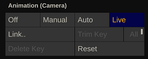
The Live option applies to all parameters in the animation channel. When the Live option is enabled, the Link option becomes available which opens the Animation Editor for the animation channels shown in the current menu.
The Link button opens the Animation Editor for the current selected animation channel, where you manage live links.
Live Animation Editor
The Live Animation Editor behaves similar to the standard Animation Editor, where in the tree view on the left side you select the channels, you want to edit / link.
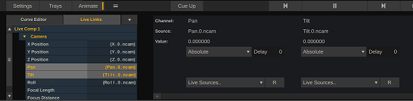
In the right panel of the editor, you link the selected animation channel to a live source by selecting a Live Link from the corresponding Live Sources dropdown.
Optionally you can set the live link to use a Delay with retrieving the value. This is similar to setting a delay with a camera tracker, which was discussed earlier. Only in this case you would delay the data for a specific parameter, rather than delaying the entire tracker data stream. This can be useful e.g. in a case where you need to project an image onto a LED wall based on the more recent camera position but at the same time render a set-extension image from a camera input - which is delayed - and need the same tracker data but of a few frames earlier.
The delay with the Live Link is set in a number of frames, not in milliseconds. Also note that when you set a delay for a channel, that delay is also set for all other selected channels. That way you do not have enter the delay multiple times.
After selecting a live source, you determine how to interpret the live link values.
- Absolute. Use the Live Link value one-on-one as parameter value.
- Invert. Multiply the Live Link value with -1 to invert the sign of the value.
- Offset. Add or subtract (negative offset) an amount to the Live Link value and apply the result to the channel parameter.
- Invert + Offset (combine the two above)
- Factor. Scale the Live Link value by multiplying it with a number.
- Normalize. Scale the Live Link value to a value between 0.0 and 1.0. Enter the minimum and maximum values that the Live Link can produce.
- Range. Scale the Live Link value to a predefined range. Enter the minimum and maximum values that the Live Link can produce as well as the minimum and maximum range the scaling should produce.
Virtual Camera
Each shot has its own virtual camera for rendering a scene that includes layers. In such a scene, the primary image (of the clip or live capture) forms the back-plate that is tied to the camera and layers exist in a 3D context. You manage the (virtual) camera settings primarily from the Camera menu.
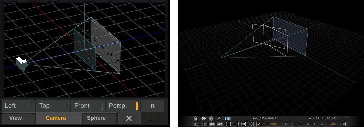
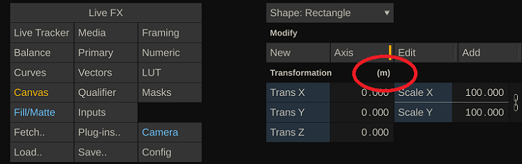
The PanZoom panel (started from the top menu bar) shows a schematic view of the virtual camera. From the PanZoom tool you can also open a more detailed representation of the virtual camera and layer-setup in 3D space by either selecting the Left-, Top-, Front- or full Perspective view. This opens the detailed view in the View port, replacing the main image view. Use various quick keys to adjust the view: Ctrl+drag or the mouse-wheel to zoom in/out of the view (note that Alt+drag zooms the viewport itself, not the perspective view camera), space+drag or the middle mouse button to pan the view (note that the middle button also works for the regular image view but only on Windows). The camera view in the PanZoom tool also uses Ctrl + drag to zoom.
The (virtual) camera in Live FX works similar as you might be familiar with in other 3D render software. There are however also differences.
- Each shot is rendered with its own (virtual) camera. Even a shot that is used inside a composition shot has its own virtual camera.
- The virtual camera is always 'looking at' / locked to the primary image, which is projected onto the far-plane of the scene. Layers behind the far-plane of the scene are not visible.
- The virtual camera is only active if the shot contains one or more layers. To use the camera, you need to explicitly activate it. In case it is activated while there are no layers yet, a single layer is automatically created.
- Layers exist in 3D space and their position determines how the virtual camera sees them in relation to the primary image.
- New layers are placed by default at the origin of the scene at a size that, given the camera default position and field of view, they exactly cover the primary image (note that the PanZoom tool shows the camera, the far-plane and the default layer position).
- Layers are marked by default as Relative, meaning that their position is relative to the virtual camera position rather than to the scene origin. As such, the layer stick to the camera view when the camera change position. When you switch off the Relative mode, the layer maintains its 3D position relative to the scene origin and independent of the camera position and rotation.
- Next to adjusting the position and rotation of the virtual camera, you can also manually adjust or live link its focal length. The focal length, together with its sensor size, determines the field of view of the camera. Note again, that this field of view determines what the camera covers of the various layers in the 3D scene, it does not affect the view of the primary clip or live capture.
- When adjusting the camera Focal Length, by default its origin position is automatically adjusted to make sure a default layer continues to cover the full primary image. You can switch off the automated camera origin by switching the camera origin to Manual.
- The camera's actual scene position is the sum of its origin position and tracker/animation offset. A (live) link with an external (physical) camera would go through the camera offset parameters - maintaining its own independent origin position.
- By default, the model is scaled in pixels and relates to the resolution of the primary image. The size of layers is also relative to this - when copying layers to a different shot with a different resolution the size of the layer is automatically adapted.
- External (camera) positional data, coming in through a live link, is in meters. To accommodate this, the virtual camera has a Pixel Scale setting. When creating a live composition from the construct this is automatically set to the width of the shot. Its actual value is not even that important as long as it is not too small and you should not change it after you placed layers at specific positions.
- In a Live FX scene the z-axis is forward/backward and the y-axis is up/down. This might differ from other 3D render software.
- Certain plug-ins link to the shot camera to use the camera data to render their effect. For this, the camera data is inherited by child nodes. That way all (plug-in) nodes can inherit from the same main camera. Note that the camera of the plug-in itself, or the camera of any node in between the plug-in and the main node, should have an active camera. They can have layers, but the camera itself should not be activated if you want it to use the camera settings of the main node.
Camera Menu
General
Activate
When you add one or more layers on a shot, a camera is created and used to render the layer(s) on top of the primary image. Note though that even though the camera is used for rendering, by default it is not marked as Active. If you want to change the default camera settings then you first have to explicitly activate it by using the Activate button. If you activate a camera while the shot does not have any layers, a single layer is created by default.
Certain nodes - such as e.g. the projection plug-in or the USD reader - have an option to use the shot camera data for rendering. When that option is set, the node will use the first active camera that is available upstream in the node composition tree. So you can have multiple USD nodes in layers on top of a Capture node, with all the USD nodes using the camera data of the parent Capture node. Each USD node can still have layers of its own. The layers are rendered with the local default camera, while the primary image is rendered based on the parent camera. This allows you to create a Global camera object for you entire composition.
Profile
The settings of a camera can be stored in a profile and easily be applied on a the camera of a new shot. When you click the Profile button, the Profile popup opens.
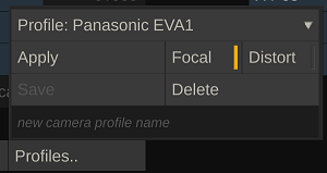
At the top of the Profile popup is a list of previously created profiles. Profiles are stored in the project database, so the list is not automatically available in a new project.
After selecting a profile, use the Apply button to update the camera of the current shot with the profile settings. If the Focal option is set, the camera lens and sensor settings are updated. If the Distort option is set, a layer with a Lens (un)Distort plug-in is added to the current shot with the lens-distortion settings from the profile.
To save a profile, type in a profile name in the textbox at the bottom of the popup panel and then click the Save button. If you enter an already existing profile name, the profile will be updated. Select the Focal and/or Distort options to include the specific data in the profile. You can only save lens distortion data, if there is a Lens (un)Distort plug-in active on a layer on the current shot.
Use the Delete option to remove the selected profile.
Calibrate
The camera Calibrate functions are discussed in the next paragraph.
Bypass
The By-pass option in the Camera menu allows you to ignore the camera position and rotation for rendering of the scene while maintaining a link with an external tracker through a Live Link.
The By-Pass option is useful, if you need to adjust certain settings in your composite and need the image to be temporarily free from any motion. Also, if you are linking to an external tracker / Live Link and forwarding this tracker information to another system but do not require the motion in the local composite.
Reset
Reset all camera settings to their default values.
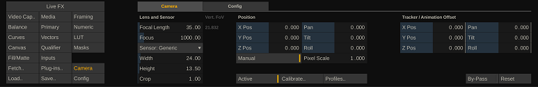
Lens and Sensor
The virtual camera Focal Length, Sensor size and Crop value together determine the camera's field of view (FoV).
(vertical) FoV = 2 x atan((Sensor Height * Crop) / ( 2 * Focal Length))
For the virtual camera to behave the same as the physical camera it is tied to, these values should be entered as accurate as possible. The focal length setting can be obtained from a calibration (see for more details about calibration later in this manual) or they can be live linked with a camera tracker. Note that the effective focal length often differs from the value on the physical lens itself.
The sensor size can be selected from a predefined list or entered as a width and height. The sensor size can usually be found in the documentation of the camera. The crop value is usually 1, although for certain output resolutions the camera might use a specific crop value. Note that in a live capture setup you are capturing the VideoIO output of the camera, which might differ from the recording settings. It is important to use the settings of the live capture signal.
The crop value can also be used when the effective focal length differs from the lens documented value, but you still want to use the latter. In that case you can calibrate the crop value against the fixed focal length.
The Zoom property of the camera is not used for the rendering of the layers. You can however maintain a value or live link it with a camera tracker, as the value is passed on as output through e.g. the Unreal Live Link and is stored as metadata for potential use in the post-production pipeline.
Position and Animation Offset
The camera has an origin position and an (animated) offset position, together which determine the actual camera position. The origin position is automatically calculated based on the image size (height) and camera (vertical) field of view so that the image exactly fits the camera frustum.
Z Distance = [Image Height] * 0.5 / tan(FoV * 0. 5)
However, you can also switch the positioning to Manual. In that case, the Z position is no longer automatically adjusted when the Focal Length is changed.
By default the (origin) position of the camera is, just like the position of layers in the Canvas menu, specified in pixels. However, most camera trackers pass the data to the offset animation position in meters. To combine the two, you need to specify a Pixel Scale. The pixel scale sets how many pixels go into a meter. This is an arbitrary scale - but for display of the camera / layer model it is important that it is not set too small or too high. As a rule of thump you can use the width of the base image. Once you set the Manual option and set a Pixel Scale, the position and of Layers in the Canvas menu is also displayed in meters.
It is important to not change the Pixel Scale after you positioned the camera and / or layers based on a meter position.
The Animation Offset parameters are intended to be animated or live linked. When using the automatic live link tracker Apply option, these are the parameters that are live linked.
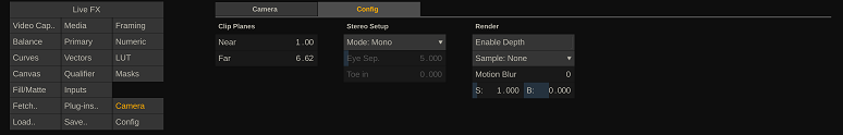
Config tab
Far Plane
By default, the Far Plane setting is dynamic. Its value is based on the image resolution and the camera's field of view. However, when you enter a specific value for the Far Plane, is will remain fixed on that value and no longer automatically update when the camera's focal length or sensor properties are altered. To revert back to the dynamic value, you reset the value by clicking the control and using the Reset option in the Calculator control.
All other camera controls are explained in the general user guide.
Calibrate
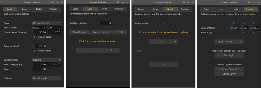
All calibration functions require you to capture live camera images. Make sure you open the calibration panel while in the player with a live capture node, preferably without any grade or scaling applied. The Camera Calibration panel can be started from the Live FX menu or from the Camera menu. The panel contains 4 tabs for various calibration tasks.
- Setup - enter the values to be used with the various calibration tasks.
- Lens - determine the lens focal length and lens distortion values.
- Nodal - determine the distance between the tracker and the camera nodal point.
- Position - determine the tracker transformation matrix from the scene origin.
Depending on the camera tracking system you use, some or all of the calibrations are done in the external tracker system and all you have to do is live link to the tacker focal length, position and rotation data. Even in that case you should still try the Virtual Ground and or / Scene layer functions from the last tab to check if the data coming in is correct.
Calibration Setup
Board
The lens calibration is done by capturing a checkerboard or aruco board under different angles. In the Setup tab you specify the boards that you use: the number and size of the squares. You can use one of the boards that are included with the installation by clicking on the example board link. Even if you print out one of the example boards, you should still measure its size as accurately as possible. Printing might have included a scaling. In general, the Aruco board has a slight preference for the Lens calibration over the checkerboard but in some cases a regular checkerboard might be needed – e.g., if the distance to the camera is relatively high.
Aruco
For the nodal point and position calibration a single Aruco marker is needed. You can again open and print the marker that is include in the installation by clicking the example link. You can also use your own marker, but it is not guaranteed that the calibration function will recognize the marker.
Sensor data
When opening the calibration panel, the sensor settings of the active shot are copied to serve as a default. The sensor specification in the calibration panel is used for any of the calibrations. Changing the settings will not automatically change the active shot camera. The camera of the current shot is only updated when applying the results of a calibration.
Calculate
The camera model uses Focal Length and Sensor size and crop to determine the field of view of the camera. This option allows you to either calibrate the Focal Length or the Crop value of the model. The calibrated value might differ from the documented value. In some cases, it is required to maintain the documented Focal Length value or the Focal Length value is coming in from a different (non-calibrated) source. In that case you can select to calibrate and vary the Crop value to ensure the camera model is correct.
Lens Calibration
The lens calibration to determine the field of view and lens distortion parameters is done by scanning a checkerboard or aruco-board a number of times under different angles. Start by setting the number of scans for the calibration. A lower number than the default might make the calibration less accurate. A (much) higher number will not necessarily increase the accuracy.
Manual Capture
-
Hold up the checkerboard in front of the camera so that the checkerboard is visible.
-
Click the Manual Capture button. If the software detects the checkerboard an orange outline is drawn.
-
Repeat this step the number of times you've set it to - each time placing the checkerboard on different position (or keep the board at a fixed position an rotate the camera). The software will indicate the step number.
-
Possibly use the Reset button to start from the beginning.
-
After doing the last capture, the software will calculate and display the field of view, focal length and distortion parameters.
Apply
Use the Apply button to update the active shot camera. Use the FL and DS buttons to respectively update the camera Focal Length and/or the Lens Distortion. The Lens Distortion is applied by adding a layer with a Lens (un)Distort plug-in and setting the correct parameters for it.
Auto Capture
Alternatively, to the Manual Capture, you can also enable the Auto Capture. Once enabled, this function will try to capture the board every 2 seconds automatically without the need to explicitly press a button. Another way to make the manual calibration process easier is to use the remote control (web) application that comes with the Assimilate Product Suite. The Remote Control can be started from the Tools menu in the Player. This opens the http server panel with a QR code that you can scan with a phone or tablet to open the application. The application has the standard remote control playback controls but also a series of function controls (F1 – F5). These can be assigned a function in the server panel. One of those functions can be to do a Capture Board for the calibration process.
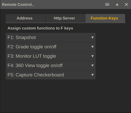
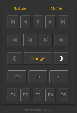
This way you can move the checkerboard to a new position and hit the function key on your mobile phone instead of having to go back to the Live FX computer to click the button in the interface.
Nodal Point Calibration
A camera tracker is mounted at an offset to the actual focal point of the camera. As such a of the camera might also result in e.g. a small xyz translation for the tracker. A tracker might also be mounted under a slight angle on the camera. To compensate for these things, you can enter translation and rotation offsets with the various tracker live links. However, manually determining these values might prove a difficult task. For one, it might not be fully clear where the nodal point of the camera is located. The nodal point calibration attempts to determine these offsets by scanning an Aruco marker a number of times under different angles.
For the calibration to work, the camera of the live capture node needs to be tied to the live link tracker that is being calibrated.
Start
Place an Aruco marker in front of the camera at enough distance to that you can rotate the camera to either have the Aruco in the center of the screen or in one of the corners. Click the Start button and follow the instructions on the panel: rotate the camera to capture the Aruco at different positions on the screen.
Use the R button to reset the calibration and start form the start. After the last step, you can still add more captures to try to increase the accuracy.
Apply
Once the calibration function has its minimum number of scans, it will calculate and display the offset values and the Apply button becomes available. The Apply option will apply the offsets to the live link tracker that the shot camera is tied to.
Position Calibration
A camera tracker might have its own coordinate system that does not necessarily match with the coordinate system you use on set. To compensate for this, the position calibration function calculates a translation-matrix. It does this by scanning an Aruco marker that is placed with its center point on the origin (0, 0, 0) position on the set. In case this position can not be used because it would get in the way of other things, you can place is at an offset from this point and enter that offset in the XYZ offset controls.
Scan Position
Click the Scan Position button to scan the Aruco and calculate the translation-matrix. If the Aruco scan was successful, the translation-matrix is applied to the active live link tracker.
Use the Reset option to clear any previous translation-matrix that was applied to the live link tracker. After that the tracker will show its raw data again.
Set Origin
Rather than scanning an Aruco marker that is placed at the origin position of the scene, you can also indicate to use the current position of the tracker as the (scene) origin.
This can be useful if you have a very small or possibly no set at all (post-production context). In that case you still need the tracker coordinate system to align so that moving forward, back, left, right is reflected correctly by the tracker.
Using the Set Origin places the camera at (0, 0, 0), while most likely the camera (tracker) is above the ground. You can compensate for this by entering an origin position for the active camera. In that case the combination of the camera origin position and the live link offsets, reflect the correct camera position.
Virtual Ground
The Virtual Ground function creates a layer at the scene’s (virtual) origin (0, 0, 0) at the size of the Aruco that was used with the Position calibration. That way the virtual ground layer should cover the physical Aruco layer. If the various calibrations are done and the camera model (Focal Length, Sensor data, nodal point, and translation-matrix) are correct, the overlay should stick to the Aruco marker even when rotating and moving the camera.
Scene Layer
This function scans for an Aruco marker that is placed anywhere in the scene and then creates a virtual layer in the scene at the same position and angle. With this you can easily place virtual objects in your scene – by adding the image of the virtual object as fill onto the created layer. In fact, if you have a node attached to the pen when clicking the Scene Layer button, that node is automatically used as fill for the new layer.
LED Wall Projection
Overview
Using an LED wall as background for recording a scene takes more than just playing back media on the wall. The media should be projected correctly where the projection considers both the position and size/resolution of the wall as well as the position/rotation of the camera that is recording the stage. If the projection does not take these aspects into account, the background in the recorded image might look distorted and wrongly scaled.
Live FX can be used to easily and correctly project media on LED wall(s). Live FX uses several elements for this which are displayed in the schematic below. The schematic gives an overview and briefly explained in this paragraph to introduce you to the various concepts involved. Each element has been or will be described in detail in this manual and separately as some elements also have their function in other contexts than projection. After discussing the elements in detail, setting up an actual projection is discussed. By then, it is easy to understand what is happening under the hood and how to manage the projection.
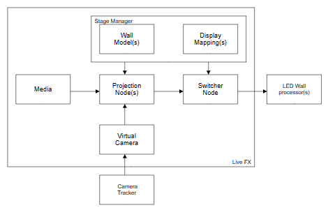
- The Stage Manager is where you manage the configuration of the LED wall(s): shape, size, resolution, and position of a wall. This creates a model of your stage.
- In the Stage Manager you also map the LED wall (models) to physical output displays (dual head and/or VideoIO).
- A Projection node comes in two flavors: 2D->Wall and Eq->Wall. Depending on the type of media you use one or the other.
- A Projection node takes in:
- Media: this can be a 2D or 2.5D pre-recorded clip, a live capture from e.g., Unreal Engine, a 3D Notch block, or a 2D render from a 3D USD scene.
- The configuration of one of the walls from the active stage in the Stage Manager
- Camera tracking data of the physical camera, coming in through a live link tracker that is tied to the virtual camera of the node.
- The projection node adapts to the resolution of the selected wall and generates the correct image based on the shape of the wall and the position of the camera.
- One or more Projection nodes (in case of multiple walls) feed into a single Switcher node. A Switcher node can playback multiple streams at the same time to specific displays.
- The Switcher node takes in the mapping information of the Stage Manager to generate a mosaic image and/or to output each wall projection to the correct display.
At the heart of LED wall projection in Live FX is the stage manager. The Stage Manager is where you create a model of your stage with the position and shape of the LED wall(s). This information is used, together with the camera position, to determine the correct image to be send to each wall. In the Stage Manager you also determine how display outputs are mapped on each of the LED walls. The Stage Manager can be opened from the Projection Setup panel in the Construct (see below) or from the Live FX menu in the Player.
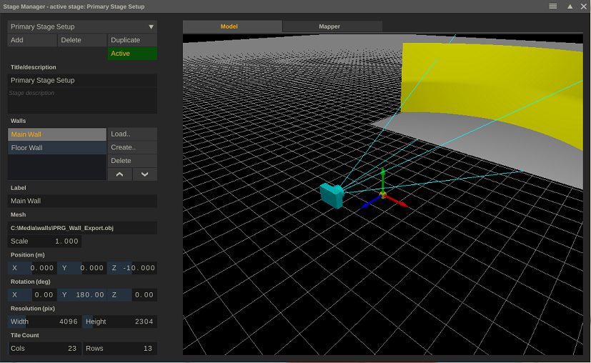
The left side of the panel contains all controls to manage multiple stages and walls. The right side of the panel show the stage model. Through the Mapper tab in the right side of the panel you link the physical display outputs to the LED walls.
Stage Management
You can maintain multiple stage configurations. Use the Add button to create a new configuration or use the Duplicate option to make a copy of the selected configuration to create a variation. The Delete option will permanently remove the configuration, there is no undo option for it.
The configurations are stored in the stageconfigs.xml file in the Assimilate settings folder. The configurations are available in all projects. Optionally, you can copy this file to other systems, however, keep in mind that the configurations have references to wall-mesh (.obj) files, which also need to be copied and be available in the same relative path on the other system.
Although you can maintain multiple stage configurations, there is only one active at any one time. The title bar of the Stage Manager panel states which stage is active. Select the Active button to make the current stage active. The button will light up green.
Wall Specifications
Each stage contains one or more LED wall definitions / models. To input the shape and size of a LED Wall, you use an .obj file. You can create and save 3D models in an .obj file in a variety of other software and use the Load option in the Stage Manager to load it in. Alternatively, use the Create button to open the Led Wall Model Creator panel.
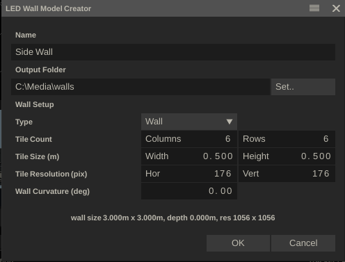
In this panel you can define the size and shape of a panel, save an .obj file to the selected output folder and add it to the stage configuration directly.
The specifications of the LED wall are defined by entering the number of LED tiles used and the size and resolution of an individual tile. Optionally you can set a curvature for the wall in degrees. Note that if you enter the curvature, the label at the bottom will show the ‘depth’ of the wall, which is the distance from sides of the wall to the centre-back. Use this if the curvature in degrees is not known and you are able to measure the distance.
There are three types of walls you can create: a standard vertical wall or a floor- or roof wall. The floor and roof walls are rotated and respond to the curvature setting by removing whole tiles from their back side to generate a saw-tooth shape.
When you press Ok the new wall is added to the stage.
The Delete button removes the wall from the stage but does not delete the underlying .obj file. Note that this action does not have an undo.
Changing the position of a wall in the list of LED wall can sometimes come at hand because the order will also be used when creating a projection setup (see below).
The Scale option can be used with .obj files that have been specified in another dimension than meters.
The position of the wall is the offset from the origin of the stage which is usually the origin of your (camera) tracking system. Both the position and rotation are relative to the origin of the wall model, which is usually in the centre bottom/back, but this might be different for externally created models.
The wall resolution is specified as the total number of pixels over the full width and height of the wall (not per tile as in the Model Creator discussed above). This resolution is used for linking a wall to a physical output.
Finally, the wall tile count is only used for generating a preview image to verify the wall mapping (see below). In case of a curved floor/roof wall, this is the count without any curvature.
Stage Model
In the Model tab of the Stage Manager the stage model is displayed. Click and drag with the mouse to rotate the model. Ctrl + click and drag to zoom in / out of the model.
The origin or the stage is represented by the colored cube/arrows: Z-axis in blue, X-axis in red, Y-axis in green. The origin of the stage usually corresponds to the origin of your (camera) tracking system.
When you open the Stage Manager in the player and there is a shot with an active camera, the camera and the camera frustum is shown in the model. This shows you what part of the LED wall(s) the camera is capturing at any point.
Mapper
Usually, the resolution of LED walls differ from the display output(s) of your system (dual head or VideoIO outputs). In the Mapper tab you configure how a LED wall relates to a physical display output. You want to prevent as much as possible that any scaling is required for the display output or being done by the LED wall processor unit.
The Mapper has the flexibility to tie walls to displays in different configurations:
- Output a single wall over one or multiple VideoIO output(s)
- Output multiple walls through an Nvidia mosaic of displays
- A combination of the above
The Display dropdown shows all available VideoIO outputs and the Dual Head if that has been enabled on the system. The combination of selected display and selected wall in the walls-list determines the combination that you are mapping.
The Map button links/unlinks the display and wall. When linked, you can set the XY Offset and Scale.
When you enable the Mosaic option with a display, you indicate that multiple walls can be mapped to the display. If the Mosaic is not enabled, then you can only map one wall to the selected display. Enabling the Map option will then automatically unlink any other wall that was previously mapped to the display.
The Mosaic option primarily meant for usage with the NVIDIA Mosaic functionality. There you create one big virtual display from multiple physical displays/outputs on your graphics card. This single big virtual display is then used as Dual Head for the system. Next, you map multiple LED walls onto that one display. Not all walls have to have the same resolution, hence the mosaic. This way the output to multiple walls can be send out as one image to the Dual Head.
Note that when you are not using the Mosaic option, then the offset and scale values are applied as regular offset and scale with that display as they are available in the Player-Settings-Monitor menu. You can adjust those settings also independently from the Stage Manager. But when doing so, the mapping for the stage configuration might become incorrect.
Dual Head vs VideoIO
In general, Dual Head output has less latency than VideoIO output. If the clip to project has little action or the scene does not involve camera motion then this might not matter. If it does, then Dual Head might be the preferred way. A combination of Dual Head and VideoIO outputs is possible. The latency difference will in general only be a few frames. If the LED walls are not joined or not captured by the camera at the same time, this should not be a problem.
Preview
The Preview option in the Mapper tab, creates a Switcher node with underlying a node that generates a test pattern: a rectangle for each LED wall tile with the row/col number. The preview meant to make sure all pixels are included in the (mosaic) output and not left out because an offset was just too high/low.
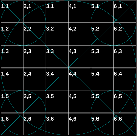
When the Preview is invoked from the Construct, the test pattern is automatically opened in the player. When already in the player, the test pattern replaces the active node. Clicking the Reset button takes back to the Construct or prior node.
Mapper Examples
To make the concept of mapping Walls and Displays in the Stage Manager more clear and concrete, here are two example mappings. The first very basic, the second using the Mosaic option.
Stage A
- Single square wall – 6 x 6 tiles, each with 200x200 resolution. So total resolution of 1200 x 1200).
- Output over 4k Video IO SDI to (also 4k) LED wall processor.
First ensure that you have the VideoIO output setup correctly through the VideoIO settings panel that you can open either from the start screen or from the Player – Settings menu panel.
Next:
- In the Stage Manager define a new stage and load or create a new wall according to the specs.
- In the Mapper tab, select the VideoIO channel from the Display dropdown and select the Map option to tie the two together.
- Since the resolution of the wall is smaller than the actual output resolution, you might have to offset the image to ensure the image is covering the wall. This depends on how / if the LED wall processor places the incoming image on the wall. An easy way to determine the correct offset is to use the Preview option. This will send out a test pattern of 6x6 tiles which should exactly cover the wall.
- The test pattern is shown through a Switcher node. On the Display tab of the Channel Controller of the Switcher node, ensure that the VideoIO channel is tied to the first channel of the Switcher node. Normally this is done automatically when using activating the Preview option.
Stage B
- Main wall with resolution of 4928 x 1936, driven by 2 x LED wall processors with 4k input (3840 x 2160). Square side wall of 1056 x 1056 pixels, driven by a LED wall processor with an HD input (1920 x 1080).
- HDMI output directly from the graphics card.
To control 3 LED wall processors from the graphics card (next to the main UI display), we first need to create one virtual display which we can use as second output / dual head in Live FX - using the NVIDIA Mosaic functions (Mosaic Technology for Multiple Displays | NVIDIA).
Rather than creating a virtual display with 3 physical outputs, we can also create a mosaic that requires only 2 physical outputs and then we duplicate the first output to be send to two LED wall processors. This saves on resources as splitting an HDMI output does not take any overhead. So, the setup that we are after looks like the image below.
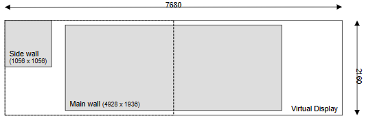
The resolution of this virtual display is 3840 + 3840 = 7680 width and 2160 in height (two 4k displays next to each other). The image of the small wall is added to the first display, which is then duplicated and send to 2 processors. Note that the default settings of the LED wall processor might have to be adjusted to show the correct part on of the image on the wall.
Once you have created the NVIDIA mosaic display, start Live FX and enable the Dual Head option in the System Settings panel which can be opened from the start-up screen.
Next:
- In the Stage Manager, load or create both walls and make sure the resolution is entered correct.
- In the Mapper tab, select the Dual Head display and enable the Mosaic option with this display. Then after selecting each wall, enable the Map option so that both walls are mapped on the Dual Head.
- Now we need to offset the walls to cover the correct portion of the virtual display. You can use the Preview option for this of do the math.
- By default all walls are mapped to the centre. The Main wall also needs to be centred vertically and the Side wall needs to be offset to the left top part of the virtual display. Doing the math with the origin (0, 0) in the center of the display we get:
- Main wall X offset = 0
- Main wall Y offset = 112 (vertical centre)
- Side wall X offset = -3312 (to top left)
- Side wall Y offset = 552
Note that the Preview option can also help to offsets the mappings accurately.
Live FX Nodes
Live FX contains all the available file-reader and effect plug-in nodes in the Assimilate Product Suite. There are however a number of nodes only for available in Live FX. These nodes are discussed in the part of the manual. Also, some nodes that are available in the regular Product Suite but do have extra meaning in a live context are included here .
Video Capture Node
At the heart of Live FX is the Video Capture node which captures a live feed through the Video IO interface. The Video IO interface supports SDI, NDI, certain USB cameras and Spout/Syphon GPU sharing with other applications. For the Video Capture node to be able to use any of these interfaces, you need to first enable and configure the interface through the Video IO Configuration panel which can be opened from the startup screen or from within the Player - Settings menu.
In the Video IO panel is explained in detail in the generic part of the manual but in general:
- Select the Device you want to use from the dropdown at the top of the panel and make sure you explicitly Enable the device.
- At the Video IO Channels section of the panel, Enable one or more Input Channels. Depending of the type of device you can also select a specific source:
- For NDI inputs, use the dropdown to the right of the channel row. This shows a list of all active NDI streams on the local network. You can also enter one or more Ip addresses in the textbox next to the refresh button to search for streams outside the local network.
- In the case of Spout/Syphon GPU sharing, the source list will show all currently available textures that are shared by other applications. Alternatively to selecting a specific source, you can select <auto> as source which means that input channel 1 will link to the first available texture, channel 2 to the second and so on.
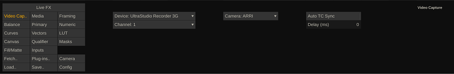
On Video Capture node, you can select the feed form the list of active Devices and from the list of active input Channels with that device. If the input is an SDI channel and the input is coming from a camera in the Camera dropdown list, then select that camera so the node can properly interpret the metadata that is send with the SDI stream.
The Auto TC Sync option allows you to synchronize multiple captured feeds based on their timecodes by buffering frames until all feeds produced the frame with the same timecode. Note that the setting is linked to the selected capture channel, not to the capture node (you can have multiple capture nodes that all link to the same channel). Also note that if you enable auto-sync on multiple channels and one channel fails to produce real-time frames, this will stall the other channels. If the timecodes of the various feeds differ too much, auto sync is ignored.
Alternatively, to the Auto-Sync you can also set a manual delay with an individual feed, in milliseconds. This is useful when you capture multiple feeds from different sources which do not have (similar) timecodes.
Full vs Video Range
In the Video IO panel, you set which YUV -> RGB matrix to use for an SDI device: either a video- or full range matrix. Different cameras require different settings when outputting a log-signal that is captured in Live FX. For most common cameras this is the matrix that should be used:
- Video range (rec709): ARRI, Canon, RED
- Full range (rec709): Sony, Panasonic
If you have a different camera then check the documentation with that camera to make sure what matrix to use when capturing the signal. Note that when capturing a linear signal (rec709) from a camera you should always use a video-range matrix.
Projection Node
A Projection node creates a projection image from its media input based LED Wall shape and position coming from the Stage Manager and the camera position. There are two types of projection nodes: 2D->wall and Eq->Wall. As the name already suggests each, depending on the type of media (2D or Equirectangular 360 media) that you want to project onto a LED wall, use one or the other.
2D->Wall
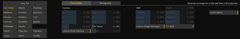
Camera/Wall
The 2D->Wall can function without the Link to Stage Manager or without Link to Shot Camera (tracker). If you disable the link options you can set all the properties specific for this node, including loading an .obj file with the shape of the LED wall. However, it makes more sense to have all that data stored in the Stage Manager once. In that case you only select which wall from the active stage configuration to use from the dropdown. Note that if you change the active stage or when you change the labels of the wall in the active stage in the Stage Manager, you might have to select the correct wall from the dropdown again.
There are several things you can control besides the Stage Manager and Shot camera. The FoV factor allows you to extend the field of view that is used from the shot camera. This is useful for frustum highlighting. By extending the FoV you create a bit of slack between the projected frustum and the actual frustum of the physical camera and as such prevent that the camera records part of the frustum highlight (or rather outside frustum dimming).
Besides using the 2D->wall node for projecting an 2D image, you can also use it to generate an alpha matte of the camera frustum. You can then use this on a layer of an Eq->Wall projection to grade the frustum. Use the Invert Alpha option to grade inside or outside the frustum.
Background
If the camera frustum does not extend the full wall, the 2D->Wall node can extend its projection to cover the full wall in different ways. You can select a way from the Background tab of the plug-in controls.
- Extend Foreground. Enabling this option will extend the color of the border of the frustum over the rest of the wall.
- By default, the image of the inner frustum is taken and repeated, using the Fit option, to extend it on the full wall. Alternatively, you can use the Scale and Offset controls to adjust the display. You can also add a different shot to the Background input of the projection node (through the Inputs menu) to be used to fit or scaled on the outer frustum display.
- If the shot that is added to the Background input of the projection node is an equirectangular shot and is flagged as such, then you can use the equirectangular (Pan, Tilt, Roll) controls to display the correct part of the shot.
Use the Gain control to dim (or if needed to brighten) the outer frustum from the inner frustum display.
Eq->Wall
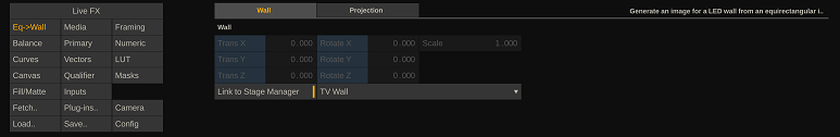
The Eq->Wall projection plug-in is similar to the 2D->Wall plug-in, except it takes in an equirectangular image to project. As such, it does not do any frustum highlighting. It does however have the option to do a Sphere- or a Dome projection, using the settings on the second tab of the plug-in controls.
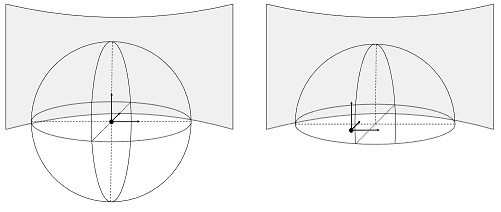
- Camera Sphere (left). The (center of the) equirectangular sphere moves with the (physical) camera (tracker). The projection is always made from the center of the sphere.
- Dome (right). The (center) position of the half-sphere (dome) is fixed and the projection camera moves with the physical camera (tracker) inside a dome. From that position, the projection is calculated for the LED walls.
For the Dome projection there are additional settings to consider. Use the XYZ controls to set the position of the center to the dome. The Radius sets the size of the dome. This size is an estimate of the actual size of the image scene. The radius is used to determine what a meter position change of the camera means inside the dome. Use the Floor setting to adjust the position where the sphere is split.
The Pan, Tilt and Roll controls are used to rotate the full scene. Note that these parameters can also be controlled from the (parent) Switcher node (if present), which then controls all underlying projection nodes for each wall in the stage.
Switcher Node
The Switcher node comes in two flavors. A basic Switcher node that can have multiple has multiple inputs and can play those back simultaneous to different displays and/or create a video wall of the inputs and play that back on any one of the display. The Projection Switcher node is a derivative of that, which in addition has a series of controls to manage underlying Projection nodes: e.g. to rotate the view of an equirectangular clip at once so that you do not have to go through each of the Projection nodes separately to update the settings.
From the Switcher node controls you can start the Channel Controller panel. From that panel Switcher node configuration is done. The configuration applies to all Switcher nodes, not just the active one.
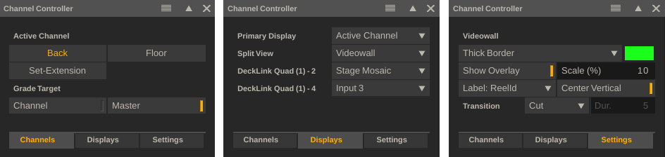
The Channel Controller has 3 tabs. In the first tab you select the Active Channel of the Switcher node and toggle the grade target. Master-mode means that the grading controls apply to the Switcher node and as such will affect all its inputs. Channel-mode means that the grading controls apply to the active channel.
In the Display-tab you set what each display should show of the Switcher node: only the active channel, a specific channel, a videowall of all channels or a stage mosaic. That last option is tied in with the Mosaic that you defined in the Stage Manager.
The Settings-tab contains various settings. The border of the active channel in a video wall, text overlays in a video wall, the transition when switching active channels and the display label for channels on the first tab: numbers or the reel-ids of the channel node.
Projection Switcher Node
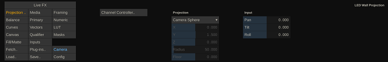
When you use the Create Projection Setup panel (discussed later) and you have multiple LED walls in your stage - a projection node is created per wall and all of those nodes are combined in a Projection Switcher node. To make it easier to control the settings of multiple Projection nodes, the projection settings are also available from the Switcher node. Adjusting the controls will affect all underlying Projection nodes. Note that you can still adjust the Projection nodes individually if needed.
Stage Matte
The Stage Matte node uses the active stage in the Stage Manager and the (virtual) camera position to generate an alpha-matte. Since the node knows if an LED wall is (partly) within view of the camera, the resulting alpha-matte can be used for creating a set-extension: extend the image on the LED wall where the LED wall stop using the live camera capture.
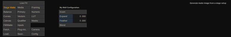
You can enhance this matte with the Expand, Feather and Blend controls to get the desired edges. The node can take in two inputs and then uses the matte to combine the images: in case of a set-extension the inputs are the live camera capture and the clip that is projected on the LED walls.
Matte Wrap
The Matte Wrap node can be used in combination with a keyer to create a Light Wrap effect.
The Matte Wrap plug-in detects the edges of the (keyer) alpha can expand it (outward or inward with a negative Size) as well as adjusting the intensity of it by using the Gain. In the example below, the first image shows the alpha from the keyer, the second image shows the alpha that the Matte Wrap generates from that, and the this image show the combined alpha.
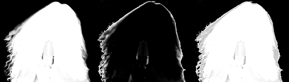
You use the Matte Warp in a separate layer after the keyer and (obviously) in the Matte of the layer. You can use the Fill of that layer to explicitly load the background image again, which then can have its own grading to even more accentuate the light wrap effect.
Live Tracker
The Live Tracker plug-in node can track a specific objects/sections in an image and make the tracker data available as live link, which in turn can be used elsewhere in your composition shot such as positioning another layer.
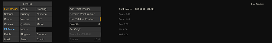
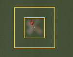
It allows you to create any number of point trackers to track a specific object in the image. The XY coordinates of each of the trackers are available as live links in your composite. The data of multiple point trackers is combined to calculate scaling and rotational data, which is then also exposed as live link.
Add Point Tracker
Add a new point tracker – the overlay of the tracker becomes visible in the image. Drag the tracker to the object that you want to track. The outer box of the tracker represents the search area. The inner box represents the object to search for. You can adjust the sizes of the boxes by dragging the outer borders. Note that the smaller the boxes the more efficient the tracker works, but the chance of the tracker ‘losing’ the object increases.
Remove Point Tracker
Remove the current selected tracker. Select a tracker by clicking the overlay of the tracker. The overlay tracker number highlights in red for the selected tracker.
Use Relative Position
With this option enabled, the node will pass the relative position to the live link – meaning the offset from the origin position. The origin position is either set when dragging the tracker to a new position, or by clicking the Set Origin button. If the Relative Position is disabled then the node passes the absolute XY coordinates in the image as live links.
Smooth
This applies a smoothing filter over the results of a tracker to filter out any jitter.
Set Origin
Takes the current position of all trackers and sets them as origin. If the Relative Position is enabled then the position of the trackers relative to this origin position is passed as live link.
Track Yaw Pitch Roll
If more than 4 trackers are active, this option tries to calculate a 3 dimension rotation from the tracker results. This option presumes that the trackers all track an object that have the same relative distance from the camera. This distance is entered as Z Value (meters) in the corresponding control.
ArUco Roll
With this option enabled you indicate that the tracked region contains a so called ArUco marker. In that case, the Live Tracker will not just track the xy position of the search region within the image but also try and calculate the angle of the marker. Although theoretically it can determine the rotation of the marker over 3 different axis, currently only the roll-angle of the marker is passed as live link.
Lens (Un)distort Node
The Lens (Un)distort plug-in node can be used to distort or undistort an image based on lens distortion parameters or by using a UV-map.
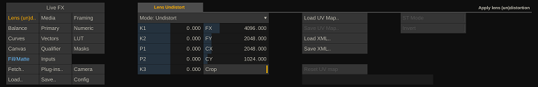
Use the top dropdown to switch between Distort and Undistort. The various Distortion parameters (P1, P2, ..) can be obtained from:
- a camera calibration and storing / applying the data from a camera profile,
- from some of the supported live link camera trackers,
- from other software by simply entering the values manually.
Use the Crop option to scale the image to remove any black borders that are created by the (un)distort. The Crop only works with the distortion parameters, not with an external UV or ST map.
The Save XML and Load XML buttons store or load the distortion parameters to / from an external file on disk.
Alternatively to using the distortion parameters, you can also use a UV map or an ST map. Use either the Load option to select a map image from disk or drag drop an already loaded map shot to the input of the Lens (Un)distort node in the Inputs menu.
If you loaded a Map through the Load button, you can clear it by using the Remove button.
Spout/Syphon GPU Share & Sender
Spout (windows) and Syphon (mac) are protocols to share GPU textures (images) between applications. Sharing images directly on the GPU limits latency to its minimum. Do note however that Spout/Syphon do not have any sync mechanism: an application always just takes the 'latest' image shared. An receiver application might already have advanced to a next frame, while the sender application has not - or vice verse. In general, when both application both run in real time (and at the same frame rate) the latency should be a maximum of 1 frame.
There are two versions of the Spout/Syphon plug-in: The GPU Share plug-in and the Sender plug-in. In the GPU Share plug-in you select one of the available textures from the Server dropdown. If the texture of an application is not listed, try using the Reload button to refresh the list. Once the texture is loaded, you can size the plug-in node to the texture size by enabling the Auto-resize option. Use the Invert-image option to flip the image in case the sending application has a different orientation for its textures. In the bottom label the format / bit depth of the shared texture is displayed.
Note that Spout/Syphon GPU texture share is also available through the VideoIO framework. The advantage of using it through the VideoIO framework is that you can also record any stream coming in through Spout/Syphon. The plug-in version is sometimes more convenient in an ad-hoc setup as it takes less configuration on forehand.
The Spout/Syphon Sender version of the plug-in is currently not available through VideoIO. You can instantiate the plug-in anywhere in your composition to share the image with another application. After instantiating the plug-in, enter a label for the shared image to be easily recognizable in the other application.
RealSense Depth (deprecated)
The Intel RealSense depth camera uses Lidar to generate a depth image. The RealSense depth plug-in captures this image and can generate a matte from it, which can be combined with an RGB camera image.
Note that the RealSense depth camera is only available for Windows. Further note this node was implemented as an experiment but that in the end the resolution of the camera, as well as the accuracy of the depth information and in dealing with the reflection of certain surfaces proved to be limited. Nevertheless – the plug-in offers a way to start using new technology in a creative way. The aim of the implementation was to use it as an overlay on the actual camera image and as such to create a dynamic mask based on the depth information which potentially could replace green screen keying. Without newer and better versions of the depth camera, further development was stopped.
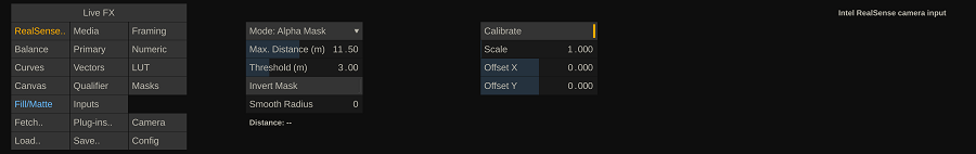
Mode
- Alpha Mask. Use the Threshold distance to generate a matte with everything further away than the threshold being fully opaque.
- Depth as Alpha. Put all depth information in the alpha channel of the image. Use the input shot of the plug-in for the RGB part.
- Depth as RGB. Generate RGB image based on the depth information.
Max Distance
The max distance is used to better reflect the depth range in the alpha or RGB shades.
Threshold
Used with the Alpha Mask mode to generate a matte from all that is closer or further away than the threshold distance. Used to mimic a green-screen setup, without the green-screen.
Invert Mask
Inverts the alpha values / mask related to the distance.
Smooth Radius
Smooth the alpha values to get rid of jitter along the edges of objects.
Calibrate
Enable this setting to get an RGB representation of the depth info so it is easier to align the depth image with the actual camera image.
Scale & Offset
Scale and offset the depth image to match the actual camera image.
Eq->2D Transformer
The Eq->2D Transformer node takes in an equirectangular image and outputs a 2D image based on a camera rotation and field of view that you set.
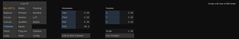
The camera rotation and field of view can also be linked to the shot camera, which in turn can be linked to a camera tracker. Optionally you can also move the inside the equirectangular sphere by adjusting the XYZ position. Note though that since this is primarily used with pre-recorded plates, adjusting in xyz too much might lead to a distorted image.
To also link the XYZ position to the shot camera, enable the Incl. Position option. Since inside a sphere the standard radius is 1, you can adjust the Scale to use a more proper range for XYZ adjustments in meters.
USD Nodes
USD (Universal Scene Description) is a format for 3D elements and scenes. The USD node load these elements / scene and uses the Pixar Hydra rendered, that is included with the installation, to render a 2D image based on the camera and object position and a range of render and lighting options. This allows you to include 3D virtual elements into your (live) composition.
Although the USD node has its own camera position controls, you can also link to the active shot camera as to fully integrate it with your composition. When you add an USD node on a layer to your composition, ensure that the layer is set to Relative, so that it 'sticks' to the camera: the USD node makes sure that at any one time the correct perspective of the 3D item is rendered to a 2D image.
Note that USD elements / scenes can be loaded directly from file just like any other media format.
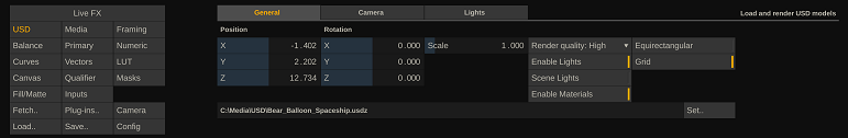
General
Position / Rotation
This determines the position and rotation of the scene. As mentioned above, if the USD node is added on a layer in a composition, the layer should be set to Relative. That way the USD node origin aligns with the origin of the 3D layer composition and virtual camera model.
Scale
Some USD scenes might be specified in a different dimension than in meters. Use the Scale to convert it into meters so it aligns with camera tracking.
Render Quality
The higher the quality setting the better the output image but also the higher the potential performance hit for the whole composition.
Enable Lights
Toggle the lights as defined in the USD on/off.
Scene Lights
Toggle additional lights (see last tab) on/off. The effect depends on the specific scene.
Enable Materials
Toggle the use of textures and reflections as defined in the USD on/off. Can be used to affect performance.
Equirectangular
This option renders the scene 6 times in all directions and generates an equirectangular output from it. The equirectangular output can e.g. be used for projection to multiple LED walls or to render out a scene and use the rendered output directly.
Grid
Toggle the display of a floor-level grid on/off.
Camera
Position / Rotation
Position the camera that is used to render the 2D image of the 3D scene.
Auto-position
Option to auto position the camera so that the scene is captured completely in the 2D image.
Link to Shot camera
This links the render camera to the shot camera, which in turn is linked to a camera tracker and controls the full composition.
FoV Factor
Only available when the USD render camera is linked to the shot camera and is a way to extend the camera frustum a bit to create some slack on the physical camera frustum on an LED wall projection to that the edge of the displayed frustum is never captured by the physical camera.
Planes
This can be used to filter out near or far away objects from the render. By using 2 versions of the same scene and adjusting the front / back planes of each you can potentially create a front and back plate that can be used with a green-screen (middle) plate.
Lights
The effect of the Ambient, Specular, Shininess color as well as the Dome Light toggle depend on the setup of the USD scene. Toggle the Auto-Position off to be able to adjust the direction of the light in the scene manually by using the XYZ controls.
NOTCH Blocks
Notch Builder (https://www.notch.one/) allows you to create 3D elements or completes scenes which can be exported as Notch Blocks. Live FX can load such a Notch Block as part of a (live) composition shot, where the various parameters of the notch block can be set, animated or linked to a live source and as such be combined with a live camera feed.
A Notch Block can be loaded directly from disk or by first selecting a Notch Block plug-in node through the plug-in browser in the player. When loaded through the plug-in browser, you are asked to select a specific Notch Block *.dfxdll file from disk. To be able to render the content of a Notch Block you need the Notch render engine installed as well as a Notch license. Certain Notch Blocks can take some time to load, the first time you open them. Loading a project with the Notch Blocks nodes in it, does not take that much extra time. However, the first time a Notch Block needs to render an image in the player it might take longer.
Each Notch Block has its own set of parameters / controls to. However, all Notch blocks have the same 3 general controls: Height and Width, which determine the size of the output of the Notch Block. Note that by default the size if the same as the size of the Live FX node but can be adjusted to e.g. a smaller size to speed up rendering (while you can then upscale the node to the composition resolution). The third general control with each Notch Block is the Layer selection. A Notch Block can contain one or more different layers of which only one can be selected at any one time. Note however that you could instantiate multiple Notch nodes in a single composition, each with a different layer selected.
Certain Notch Blocks can contain properties that are exposed as Live Links (similar to the output of the Live Tracker). These Live Links can in turn be used to control and steer other aspects of the composition. Check the Live Animation editor for available Notch Block parameters.
NotchLC
Next to rendering Notch Blocks, Live FX also supports playback of (QuickTime) media encoded with the NotchLC codec. The NotchLC codec is used to ensure real-time playback due to its GPU optimized encoding model. There is also a NotchLC encoder available for SCRATCH to transcode any media into this format. Contact support on the known email address for more information
Live Composition Setup
Many of the individual compositing elements and function available in Live FX come together in the Live Composite Setup panel. This Wizard type of function is available from the Construct main menu and helps you to setup complex live (green-screen) compositions with just a few clicks.
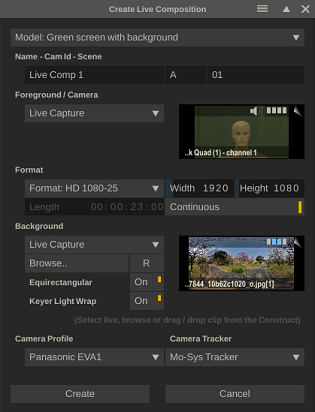
Start by selecting type of composition you want from the Model dropdown. The various options are self-explanatory.
Next, set the Name for the composition as well as the Camera-id and Scene designation.
Select the camera that you want to capture from the dropdown that lists all available VideoIO inputs. Note that it is possible to select a different capture channel or even add multiple live capture nodes into your composite at a later stage.
In the Format options you specify the resolution and framerate of your composite. The framerate should be the same as the live capture. A live composition can be Continuous (no ending) or have a specific Length. Note that even if you specify a specific duration, playback of the composite is always looped, and any recording will continue until explicitly stopped.
Select the background for your (green screen) live composition. There are different options:
- The background can be an existing clip. Use the Browse option to load it directly from file or drag-drop the clip from the Construct into the proxy area.
- Alternatively, the background can in itself be a live capture coming from another camera or a live capture coming from other software.
- If the background image is an equirectangular image, then make sure it is marked as such if not already by default.
- If you do not require a background at this point but one was selection in a previous session, use the Reset button to clear it.
Any green-screen with background composition, involves a key /qualifier. Enable the Light Wrap option to automatically include a Matte Wrap node to create the light wrap effect.
A live composition is likely to use a Camera Tracker. The dropdown lists all supported trackers (live links), whether they are already active or not. If a tracker live link is not yet active is be activated automatically. The first available tracker in the selected category is used to live link to the virtual shot camera. If the background clip is an equirectangular clip, then a Eq->2D Transformer node is included in the composition which links to the main shot camera.
For most live compositions to work correct, a calibrated (virtual) camera is needed. Make sure you create a camera profile after a calibration. Selecting an existing Camera Profile with the live composition setup will speed things up enormously.
Once you hit Create, a composition node is created, which is placed in the first empty slot in the construct and then opened for playback and further setup in the Live FX Tab. As mentioned, all options that have been set in the Create Live Composition panel can be modified in the Player.
For some compositions additional steps are required. E.g. when using an Unreal Engine background, you need to make sure Unreal is running the correct project and the project contains the Live Link plug-in so the Live FX can sync the images of unreal with the live camera images that are being captured. Various tutorial videos are available from the Live FX support website that show the possible workflows.
Live Projection Setup
Similar to the Live Composition panel there is also Live Projection Setup panel to help you setup relatively complex projection composition shots with just a few clicks. This function is also available from the Construct main menu bar.
Steps
The first step in creating a projection setup is select a stage-configuration from the Stage Manager. If there are not stages available yet, then you can open the Stage Manager to create one. The selected stage-configuration will automatically become, if not already, the active one. Note that you can create a projection setup without the Stage Manager but then you will have to manually enter all LED wall specifications in the projection node.
Next, set the Name for the composition as well as the Camera-id and Scene designation.
The clip that is to be projected on the LED wall can be:
- A pre-recorded plate of any of the supported file formats, any resolution and framerate. Use the Browse option to select a file from disk or drag/drop an already loaded clip in the proxy area.
- A Live captured image from other software such as a game render engine like Unreal or Unity. Select the desired from the VideoIO capture list.
- A 3D scene rendered by a USD of Notch block node. Use the Browse or drag/drop option.
- If the image that is to be projected is an equirectangular image, then make sure it is marked as such if not already by default.
It is recommended to do a camera calibration and store a Camera Profile for the camera that is used to record the projection. Select the profile from the dropdown rather than having to enter all data after creating a projection setup, will save a lot of time.
The Camera Tracker dropdown lists all supported trackers (live links), whether they are already active or not. If a tracker live link is not yet active is be activated automatically. The first available tracker in the selected category is used to live link to the virtual shot camera.
When enabling the Frustum Highlight toggle, the active camera frustum will be displayed in the projection. This is done by slightly dimming the outer frustum. The display of the main image in the inner frustum is not adjusted.
When projecting an 360 image (pre-recorded plate), you have the option to us Spherical or Dome projection (see for more information the description of the Projection node).
Capture scene
To live review the result of the scene, you can capture the image of the physical camera. Select the correct channel from the Live Capture dropdown list. This will create an additional channel in the resulting Projection Switcher node. Potentially you can also use this for recording. Note though that you do not want to get in the way of regular playback in case the resources of the system are limited and the media + grades become extensive and complex.
Enable the Set-extension option to add a Stage-matte node with the live capture so the projected image is (virtually) extended if the camera frustum does not fully overlap the LED wall. Note that usually a camera capture introduces a few frames delay. That means that the set-extension clip should take this into account. Set the Frame-delay so that the correct back plate frame is combined with the correct captured frame. You can adjust this at any point in the player – in the Fill/Matte menu of the Set-extension layer.
Projection Composition
Click the Create button to create the projection setup. This composition is placed in the first empty slot on the construct and the nod is opened in the player. The exact layout of the Projection composition depends on your LED wall configuration in the Stage Manager and the if you added a live capture / set-extension.
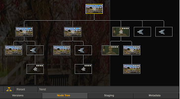
The Projection composition node will likely contain the following elements:
- Switcher node at the root, with for each LED wall output a channel + optionally a channel for live capture. The Switcher node is tied to the camera tracking.
- Each channel has a Projection node, which in turn has the source clip as input. The projection node uses the Stage Manager and is tied to a specific wall. The Projection node uses the virtual camera settings of the Switcher node.
- In case of frustum highlighting. The Projection node has a layer with a 2D->Wall matte plug-in that dims the outside of the camera frustum.
- In case of a Live capture, an extra input/channel is added to the Switcher node. If no set-extension is used, the capture node is used as the channel input. For a set-extension, the Stage-Matte is used as input, which in turn takes the live capture node and the source clip as input. It uses the Stage Manager and Switcher node camera settings to render its output.
When only dealing with a single LED wall and no live capture then the composition the Switcher node is not included, and the channel projection node becomes the root.
Composition Assemble
(Live FX Studio)
In the paragraph about the recording options in the Live FX menu in the Player, the option to record the clean sources (rather than the full graded composition) was briefly discussed. In this paragraph the workflow to start with a live composition, create and tweak an offline composition and ultimately create the final online composition is discussed. The workflow is displayed in the diagram below.
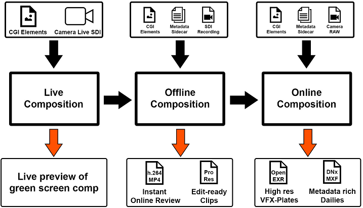
With the Record: Source Capture option, the Auto Load Clip and the Write Metadata Sidecar options enabled in the Live FX menu, every recording of a live composition shot is automatically transformed into an offline composition shot, where:
- A full copy of the original (composition) shot is made.
- Any live capture node inside the composition shot is replaced with the recorded source.
- Any live link animation is replaced with data from the side car file and put in an animation curve for the specific parameter.
- The shot is tagged as an offline composite.
An Offline Composition can be worked on as any normal composition: e.g. smooth animations or adjust grades. Once the high resolution camera media has been offloaded from the camera and loaded into your project, you can create the Online Composition. To transform an Offline Composition into an Online Composition (or directly a Live Composition into the Online Composition), you use the Online Composition Assembler which is available from the Online Compositions button in the Construct menu.
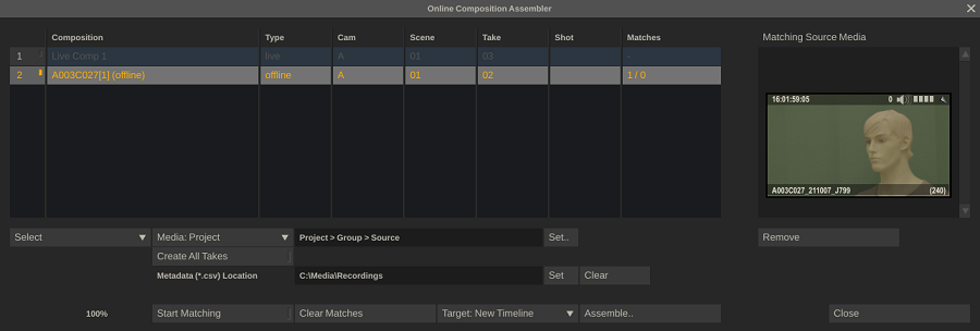
The panel lists all Live and Offline composition shots in the current timeline. If a shot is selected int he timeline it is enabled in the list, otherwise it is disabled. This way you can quickly transform just a single node. Click the button in the first column in the list or use the Select option below the list to alter the selection. The next step is to point the Assemble function where to look for the Online media: either select a specific group of timeline in the project or use the Media drop down to select a specific folder on disk. Then make sure that you point the Assemble function to the correct folder with the sidecar files with (animation) metadata. The function will match the correct files with the correct composition.
After pointing the function to the correct locations for media and metadata, start the matching function and tell it where to put the results by using the Target drop down. The Assemble button will start the actual creation of the Online Composition:
- Copy the Live or Offline composition.
- Replace live capture nodes or offline recordings with the online high resolution camera media.
- In case of a live source, replace the live links with the animation data from the sidecar file.
- Place the new Online Compositions in either a new timeline, as versions in the same slot as the Live / Offline compositions or attached to the pen from where you can drop them anywhere you want.
Note that you can use Create All Takes in one go when going directly from a Live Composition to an Online Composition. However, you do need to make sure that the Online media has to correct cam-id and scene-number metadata to match with the Live Compositions as a timecode match will not work.
In the right part of the Composition Assembler you can see the matched Online shots that were found with the Live or Offline Composition. If for some reason you find there is a wrong match then either use the Remove button to remove the individual shot or use the Clear Matches button to clear all matches with all nodes in the list to start a clean new match round.
DMX
With the DMX module in Live FX you can control on-set lights, based on the media that is played back on the LED wall, the background used with a green-screen setup or tied to any other media upon which the lighting should act. You start the DMX module from the Live FX menu in the player or from the Tools dropdown menu in the player top menu bar. Some know how about DMX is required to operate this module. Although any low-level hardware aspects might not be needed, a basic understanding of the concepts of DMX channels, -universes, -controllers and -devices is needed to operate the module. On the web are various starter tutorial sites and videos available.
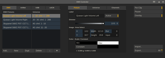
Configuring and using the DMX functions involves 3 steps:
- Connecting to DMX controller(s) / device(s).
- Configure Fixture(s): select or create lights and the channel layout to be used with the lights.
- Link the light to a specific part of an image to set its color dynamically during playback of the media.
DMX Controllers / Devices
The DMX module supports three interfaces for connecting to a DMX device:
- USB – supporting Enttec devices which in turn connect to a light/fixture using XLR.
- ArtNet. This uses Ethernet to connect to one or more DMX devices. This device might be a light/fixture with the Art Net interface build in or it might be a controller that in turn connects to the lights/fixtures through a serial connection.
- sACN. This also uses Ethernet to connect to a DMX device but can use multi-cast option where the DMX Universe is part of the Ip address, which makes settings up a high number of fixtures a bit easier.
To manage the connections, use the corresponding tabs in the DMX panel. When starting the DMX function, the software automatically scans for Art Net and USB devices. Since sACN uses a multi-case protocol, it does not specific (listening) devices. Use the Refresh button to scan again if you connected new ArtNet or USB devices to the network/computer while the panel was already started.
Note that all three protocols can be used at the same time. Each protocol is tied to a one or a range of universes. The data for any fixture that is linked a universe is send through all protocols that are also tied to the universe.
ArtNet
Adapters
If the system has multiple network adapters, then select the adapter to scan for ArtNet devices.
Active Nodes
All ArtNet devices/controllers found are listed in the Active Nodes table. That table also shows the Ip address of the nodes as well as the DMX Universes the nodes are using.
Sub-Net
An ArtNet device can have a specific sub-net set to be used in addressing the device. If you want to address that device, then the Sub-net settings should have the same value. Usually this is 0. The main Net number for the DMX ArtNet module in the software is currently always 0.
Port Universes
By default the DMX ArtNet implementation has 4 output ports, where each port can address a different DMX Universe. You can alter the DMX Universe to any value in the 1-16 range.
USB Devices
All devices found are listed in the table where the name and serial number are displayed as well as the DMX Universe that the device is linked to. You can change the DMX Universe by clicking the column and entering a different number [1-16].
sACN
The sACN protocol need to be explicitly enabled using the Multi-cast on/off toggle. In case the system has multiple network adapters, select the Adapter to use to send the data over. Next, specify the universe range to be used with the protocol. This can be any range in between 1 and 65536. Any data for any fixtures that are tied to a universe in that range is send with sACN.
Fixture Setup
Manage Fixtures
The first tab on the DMX Controller lists all the available fixtures / lights. The second set of tabs (Fixture, Universe, Channels) contains the settings of the selected fixture.
Add
This opens a new panel with a list of predefined fixtures. The first time you open this list, it will show empty, but a download will automatically start to retrieve a list of existing fixtures. When the list is populated, select a manufacturer, the fixture and then the mode it should operate in. This will then determine the DMX channel layout for the fixture. Click OK to add the selected fixture to your setup.
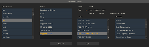
New
Click New to create a new ‘empty’ fixture for which you will enter the DMX channel layout yourself.
Dupl
Duplicate / make a copy of the current selected fixture.
Delete
Remove the selected fixture from your setup.
Up / Down
Move the position of the selected fixture in the list of fixtures.
Configure Fixtures
Universe
In the Universe tab you set the number of channels that a fixture uses and assign the fixture its position within one or more DMX universe(s).
- The Universe number assigns the fixture to a specific universe.
- The Start number assigns the first channel number within that universe the fixture uses (a universe has a max of 512 channels).
- The number of Channels specifies how many channels the fixture uses in total.
- The Globals counter indicates how many of the channels of a fixture are only used once (at the end) if the fixture has a repeat count. Some fixtures are build up of a number of lights. You only specify the single light channel usages and then use the Repeat in Universe control to indicate how many times this light is to be repeated. The global channels are not repeated with each light and only added after the all the repetitions. The global channels are usually used to control a setting that applies to all repeated lights.
- The Repeat in Universe specifies how many times the channel layout of the fixture is to be repeated. A light-beam can consists of e.g. 24 lights, each using 6 DMX channels. The Channels counter would indicate 6 while the Repeat in Universe would indicate 24.
- With the Repeat the Universe setting you can duplicate the specified universe. To follow the above example. If you would have a total of 16 of the light-beams (mounted together), then you do not have to specify them each separately, but can just set the Repeat the Universe to 16. If the first beam was set to Universe 24, the next 15 beams would use universe 24 - 40. This functionality is particularly useful with the sACN protocol that multi-casts the dmx data based on universe number.
Color Sampling
The Distribute, Segments, Order and Inverse controls in the Universe tab are used to determine how the color for the fixtures is sampled from the active clip that is playing. Each fixture is can be tied to a specific section (rectangle) of the image playing. In the case that a fixture is made up from multiple lights and/or you have been using the Repeat options, then you also need to specify how the color sampling maps to the various lights.
The first option is the either Duplicate the color sampling and use the same average color for all repeated lights or to Distribute the color sampling area into multiple smaller areas where each light have its own section: by default the rectangular area is split up in a single row of smaller areas. In the figure below you can see how to adjust the sample mapping.
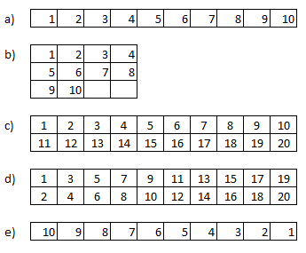
Figure a) displays shows the default distribution of the sample area when using a repetition of 10. By using the Segments control you can adjust the number of rows that are using in the sampling area. In figure b) Segments is set to 3 and generate a pattern of 3 rows and 4 columns - leaving 2 samples not-used.
In some fixtures the repeated lights are not following a row-after-row pattern (figure c) but the lights are ordered per column (figure D). In that case you can use the Order dropdown to specify an column-order rather than a row-order. This also works if the fixture contains more than 2 rows of lights.
Finally you can Invert the order of sampling - figure e) by using the corresponding option.
Channels
Each property of a fixture is controlled through one or more DMX channels. In the Channels tab you can specify which value to use for each DMX channel. This can be a dynamic value based on active color sampling or it can be a static value. The Channels lists the channels that you specified in the Universe tab. The first column specifies the channel index. If a channel is a Global channel then it is marked as such in this column. The second column specifies the dynamic value to be used for the channel. In the third column you can set a static value that is to be used for the channel. This can be any value between 0 - 255. The documentation of the fixture will specify which values can be used and their meaning. Finally, in the last column you can (optionally) enter a label that clarifies the function of the channel. The possible types of dynamic channel value are:
- None. The channel value is not dynamic, the (static) value used is specified in the value column. If no explicit value is set, then 0 is used.
- Dimmer / Dimmer fine. Control the brightness of the fixture. The value is determined by the slider control on the Fixture tab. If the fixture allows for a two channel dimmer function, for more fine grained control, then use both the ‘fine’ and regular option on subsequent channels.
- Red / Red fine. Control the Red color channel of the fixture. The value comes from the image (area) that the fixture is linked to.
- Green / Green fine. Control the Green color channel of the fixture.
- Blue / Blue fine. Control the Blue color channel of the fixture.
- White. Control the white color channel of the fixture. The value comes from the luminance of the image (area) that the fixture is linked to.
- OSC. The value is found from the OSC Source Live Link. This requires that the OSC Source Live Link is active. In the description column you enter the OSC tag to be used.
Fixture Control and Color Sampling
On the Fixture tab you control the fixture general settings.
Name
Enter / change the fixture label.
Active
When de-activating a fixture that is in a universe with other fixtures that are still active, all channels on the deactivated fixture as set to 0. If there is no other active fixture within that universe then no new data is send to the fixture.
Dimmer
Adjust the brightness of the selected fixture. This only works if the fixture has channels that are linked with a dimmer function.
Image Area Select - Color Sampling
Each fixture (unless it is set to have a fixed color) is tied to a specific section in the image of the active node in the player. In the Viewport an overlay is displayed that marks this section. This section of the image is used to sample the color for the fixture: the average color of all pixels in the image section. You can adjust the size of the image section of the position by either adjusting the numeric control on the Fixture tab or by dragging the overlay in the Viewport.
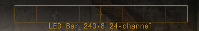
Note that in some cases you need to specify which input of a composition node to use to sample from. E.g. when using a Switcher node, you want to tie the color sampling for a fixture to a specific channel in the Switcher node. Use the Input control to specify which channel / input to use. The value 0 indicates to use the main / root node.
Color Scale / Constant
Use the Min/Max color controls to set a minimum / maximum color that a fixture should receive. When the min/max color is set, then the calculated average color of the image area is scaled within these minimum and maximum colors.
Rather than determining the color for a fixture dynamically from the playback clip, you can also set a constant color for one or more fixtures. For this, enable the Constant option and use the color pot next to it to determine the color for the fixture.
Other DMX Controls
The DMX module has a number of generic functions to control its behavior.
Per Clip
The general fixture setup is stored per project. The settings on the Fixture tab (Active / Dimmer / Area select / Scale / Constant) for all fixtures are however by default stored per clip. If a clip does not have any DMX settings with it, the last known settings are used. However, any change that is made to the settings is only stored with the current active clip. Moving back to an earlier clip will restore the settings for that clip. If you switch the Per Clip setting off, then settings are no longer stored per clip but only a single set of settings are maintained for all clips.
Pause
(Temporarily) switch off sending any DMX data to the active devices.
Overlay
(Temporarily) switch off drawing the area select overlays in the View Port.
Import / Export
DMX settings are stored in the project database. Use the Export / Import options to save the DMX settings to an external file and load them into another project. Use the All option to export the settings of all fixtures or only the current selected. This then also determines the extension of the file: ‘*.fdmx’ for a single fixture vs. ‘*.admx’ for all fixtures.
LED Wall Control
In most cases when outputting to an LED wall, the grade and look is all done from withing Live FX. However, it can be very useful to have control over the overall brightness and color temperature of the LED wall. The LED Wall Control utility in Live FX, which is available from the Tools menu in the Player top menu bar - can interface with the Tessera LED Wall Processors from Brompton Ltd.
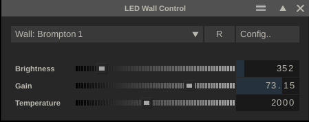
From the control panel you can adjust the overall brightness of an LED Wall as well as the Intensity Gain and Temperature settings. With the Config option you can define multiple walls, each referencing one or more processors by just adding lines to configuration file. Start each line with a name / wall identifier and add one or more IP-addresses of the processors associated with the wall - separated by a comma.
Wall 1, 10.10.10.1, 10.10.10.2, 10.10.10.3
Wall 1, 10.10.10.25, 10.10.10.26
One of the advantages of adjusting the overall brightness of the LED wall rather than adjusting (the grade on) the outgoing signal is that you can use more of the available (limited) bit depth for the nuance of the grade.
Keyers and Alpha Output
Keyer Pre- and Post-Options
To be able to create a key in a live context without having to create multiple layers and/or use additional plug-ins, the Qualifier menu has been split in a separate color selection tab and a pre- / post-options tab with a set of new functions.
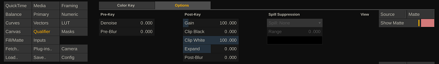
The new functions are:
- Denoise pre-option, to remove noise in the source image to create a cleaner key.
- Clip Black / White post-options, which basically works as a lift-function on the alpha channel from the key, clipping the alpha at a certain level with minimal effect to the existing edges.
(all other qualifier functions are described in the main manual)
Alpha output over SDI / Dual head
Live FX offers the option to output the alpha channel of a (live capture) shot as a black and white image through an SDI output or through the dual head GPU output. This offers an opportunity to use the qualifier / keyer function of Live FX – including all layering and garbage mask functions, plug-ins and compositing options – for other systems downstream in the pipeline. The SDI output can be gen-locked and contains the active timecode of the shot / live captured input. To output the black/white matte just select the option with the Display settings in the Player – Settings – Monitors menu.