GENERAL
The external control surfaces are a great way to increase the speed of color grading in SCRATCH. The current supported panels are: Tangent (CP200, Wave, Ripple and Element) and AVID Artist Color.
Note: The Tangent Elements, Ripple and AVID Artist Color panels require you to install their own driver and communication layer application software that comes with the panel.
PHYSICAL CONNECTIONS
USB/SERIAL INTERFACE
To Connect the Tangent Wave using the USB/Serial interface, simply power on the device and connect the USB cable to an available USB port on the SCRATCH system. Once connected, the device installs itself automatically, including (if needed) a Virtual COM port (VCP) driver to connect to the JL Cooper device. From here you can proceed to the section on CONFIGURING THE CONTROL SURFACES. If, after following the steps to configure the control surface, you still are not able to establish communication with the device, see the section about TROUBLESHOOTING CONTROL SURFACE PROBLEMS for more details, later in this chapter.
ETHERNET INTERFACE
In an Ethernet configuration, each control surface is assigned an IP address on the network. This IP address identifies the control surface on the network, so that SCRATCH can communicate with it. In most cases, this really just means the control surfaces and computer must have the same first three numbers in the IP address. For example, 192.168.10.xxx. This will be covered in detail in the section about CONFIGURING THE CONTROL SURFACES later in this chapter.
The control surfaces need to be on the same physical network as the system but can also be connected directly to the system in a stand-alone setup or if there is a second network adapter available in the SCRATCH system. It’s recommended that you keep the control surfaces as close to the computer on the network as possible. Meaning, there are a minimal number of network switches or other network appliances in between them. If necessary, consult a network administrator or IT manager for proper network setup between the SCRATCH computer and the Ethernet control surfaces.
If the network has a DHCP server that assigns IP addresses, it is possible to just use this to assign the IP address to the control surfaces. If however, there is no DHCP server, or if you are connecting the control surfaces directly to the computer and there is no other network connection needed, assigning the IP addresses manually is recommended.
CONFIGURING THE CONTROL SURFACES
Using the Panels Setup Settings in the SCRATCH Preferneces dialog, you can initialize and configure one or more panels and instantiate a set of control mappings.
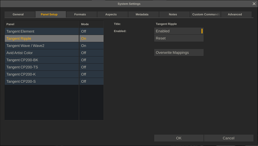
In the left part you select the panel to configure. The right side of the dialog shows besides a number of common functions the set of configuration parameters that differ per panel type.
COMMON FUNCTIONS
Enable
Toggle to enable / disable a panel
Reset
Reset all configuration values to their default values
Overwrite Mappings
When you enable a panel the first time - a set of default control mappings is activated which you can customize once inside the Player. When you enable another panel these mappings are not overwritten by default but require you to explicit click the Overwrite button.
CUSTOM CONFIGURATION
Tangent CP200 Panels
For the Tangent CP200 panels, you need to provide the Serial Number ID for each panel. The serial number ID is shown on the panel’s display when it is powered on. Every panel has its own unique ID which needs to be set for every panel that you enable. The remaining sections of the configuration describe the IP address and other network information for the panel. If you are using DHCP you only need to enable that setting -though you need to set it for every panel that you enable. Alternatively you need to setup the IP address, Netmask, Gateway and port manually.
In case you set the IP manually and if the computer and panel are the only things on the network, it’s recommended to leave the IP addresses at their default values. If the Tangent panels will be on a network with other computers, you need to get the proper IP address, gateway and netmask information from your network administrator.
Tangent Ripple, Wave, Elements and Avid Artist Color
No additional configuration settings are required, but note that the Tangent Element and Ripple panels require TangentHub to be installed. The Avid Artist Color requires EUControl to be installed.
http://www.tangentwave.co.uk/support.asp
http://euphonix.avid.com/artist/ux/euphonix/artist_downloads.html
CUSTOMIZING THE CONTROL SURFACE IN SCRATCH
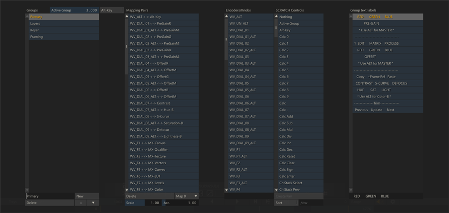
THE CONTROL SURFACE CONFIGURATION INTERFACE
Once SCRATCH is running, the Control Surface Configuration Interface is available from inside the Player under the Settings Menu. Clicking on the Configure Panels button opens the Configuration Interface. The interface has four main sections: Groups List, Mapping Pairs List, Encoders/Knob- SCRATCH Controls List and Group Text Labels.
Note: All SCRATCH controls are active while editing the Control Surface Configuration! Moving a control on the panel adjusts the parameter to which it is assigned. Because of this, it is recommended that any adjustments to the panel mappings be made on a non-vital Construct; this avoids any negative affect to critical work that has been done as part of an active job.
UNDERSTANDING GROUPS, PAIRINGS, AND MAPPINGS
The basic building block of panel mapping is the Mapping Pair. This is a link between a control on the panels and a function within SCRATCH. The value of the SCRATCH function will be modified when the panel control is changed, based on values that are set up as part of the Mapping Pair.
There are a limited number of controls on the panel, and many functions that can be controlled within SCRATCH. You can create multiple Groups of controls that allow you to re-assign some or all of the controls on the panels.
A good analogy is to think of Groups as transparency overlays on the panels.
For example, think of a printed image. Now, picture several sheets of transparent plastic laid over the image. Each piece of transparent plastic can have a new image on it, which will obscure part of the image below. However, where there is nothing on the transparent plastic, you can see through to the image below.
The concept is the same for panel mapping. Each new group of Mapping Pairs overlays on top of the group below it. The order of the groups can be seen in the Group list on the left side of the Configuration Interface. At the top of the list is the Default Settings. This is the base group where most controls are assigned. This is the equivalent of the printed image in the picture analogy. Each additional group can have new functions assigned to a panel control, which will ‘cover up’ the function assigned to that same control in a lower group.
In this way, you can create groups of panel mappings which expose certain functionality within SCRATCH based on the task you are doing.
For example, a Group called PRIMARY can be dedicated to primary color grading. All of the functions that are mapped to the panel will be for controls such as Lift, Gamma and Gain, Offset, Pre-Gain etc. Then, you can create a new Group called PAN-SCAN, which re-assigns some of the controls to functions such as Image Scale, Offset and Rotation. You can also create another Group called SECONDARY, which dedicates controls on the panel to tasks that are specific to secondary color grading, such as Layer selection and positioning, Qualifier color selection, and so on.
Now, when you want to work on primary grading, you switch to the PRIMARY group and you have all the tools for primary grading available. When it’s time to do secondary work, switch to the SECONDARY group, and now the panel controls are specialized for secondary color work.
This is just one example of how Groups can be used. The method is completely flexible and can be configured to your specific way of working. The important point to remember is that any panel control not assigned a specific function in a Group, will keep the function from a lower group.
CHANGING THE ACTIVE GROUP
Each group is numbered, starting at zero, to identify it. The group’s position in the Group List determines its number. You can see the currently Active Group number in the Numerical Slate above the Group List. The Active Group is a parameter that can be mapped to a panel control. If you are going to use multiple groups, you must have at least one control mapped to the Active Group function, so that you can easily switch between Groups.
For example, in the default panel mapping for the Tangent panels, the F1 and F2 buttons on the Tangent CP200-BK are mapped to the Active Group. The F1 button increases the Active Group number by one each time it is pressed, and the F2 button decreases the Active Group number by one each time it is pressed. This allows you to easily move forward and backward between Groups, without continuously pressing one button to go all the way through the Group List and loop around.
CREATING A NEW GROUP
To create a new Group, click the NEW button at the bottom of the Groups List. This will create a Group called New Group at the bottom of the Groups List. You can rename the Group by clicking in the Text Slate at the bottom of the Groups List, and typing in a new name.
Tip: Be sure to press Enter on the keyboard to accept the new name.
You can remove an existing Group by selecting it from the list, and then press the DELETE button at the bottom of the Groups List. Use the arrow UP and DOWN buttons to change the position of the current group in the Groups list.
CREATING NEW MAPPING PAIRS
To add new pairs to this list, select the proper Group in which you want to create the mapping from the list on the left side. With the Group selected, you can select the button or encoder from the Encoders/Knobs list, and then select the SCRATCH control you want to be affected by that button/knob from the SCRATCH Controls list. Press the Create Pair button at the bottom of the Scratch Controls list, and a new Mapping Pair will be created in the Mapping Pairs list.
Tip: SCRATCH automatically selects a panel encoder, knob, or button when it is pressed or moved. This allows you to easily select a panel control without searching through the list. If a Mapping Pair already exists for that panel control in the current Group, the Mapping Pair will also be selected.
MODIFYING AN EXISTING PAIR
Each Mapping Pair has three values associated with it: Scale, Acceleration and Map. These values can be changed at any time by selecting the Mapping Pair and entering a new value.
Scale
The Scale value determines the overall sensitivity of a panel control. Each increment of the panel control is multiplied by the scale, and that is the amount the SCRATCH parameter will change. By increasing the Scale value, you can increase the SCRATCH parameter more quickly, but you lose some ability for fine control. The Scale value can also be set to a negative number. When applied to Knobs or other encoders, it is not necessary to assign a separate positive and negative control. The encoder automatically increases or decreases the value. However, using a negative value reverses the behavior of an encoder so that a counter-clockwise movement will increase the value, rather than decrease it. You can also assign negative Scale values to buttons to decrease a value. An example of this is the Active Group buttons in the Default mapping. One button has a positive Scale, while the other button has a negative Scale. The end result is one button increases the Active Group value, and the other button decreases the Active Group value.
Acceleration
The Acceleration value controls how quickly the SCRATCH parameter changes, depending on how fast the panel control is moved. This is most frequently used for encoder knobs or trackballs so that a quick movement increases the SCRATCH parameter by a large amount, but a slower movement adjusts the parameter by small increments. This allows for very fine control when moving a panel control slowly, but more drastic changes when moving a panel control quickly. You can adjust the Scale and Acceleration values to get the behavior you want from a particular control.
Map
Several SCRATCH controls have multiple channels or Maps. For example, the Lift control has three Maps; one for the horizontal axis of the color wheel, one for the vertical axis of the color wheel, and a third for the master adjustment. Each of these Maps must be assigned to a different panel control. If you look at the default panel mapping under the Default Menu Group, there are three Mapping Pairs associated with the Lift control. They are assigned to Trackball 1’s X, Y and Z axes. If you select one of the Mapping Pairs, you will see the associated Map value. Notice that the Map value is different for each axis.
Most SCRATCH parameters have two Maps; Map 0 is the parameter’s value and Map 1 is the reset for the parameter. So, creating a Mapping Pair using Map 0 links the panel control to the actual SCRATCH parameter’s value, and creates a second Mapping Pair (usually using a button); using Map 1 links that panel control to resetting the SCRATCH parameter. In the case of eg. a knob, rotation can be set to Map0 and pressing, set to Map 1 would result in a reset.
A complete list of each SCRATCH Control and its associated Maps is available in Appendix C - Panel Mapping.
FINDING SCRATCH FUNCTIONS: SORT AND FILTER
The number of mapable SCRATCH functions is quite extensive which can make finding a particular function more difficult. To make this easier you can use the Sort and Filter options at the bottom of the SCRATCH Controls list. The Sort button will sort the current list by name alphabetically. Clicking it a second time will revert to the default grouping sort. By entering a text in the Filter text-slate and pressing Enter, the list of controls is shrunk by applying the text filter.
EDITING THE GROUP TEXT LABELS
The text that appears on each display can be edited to represent the functions currently available. Each Group can have its own text display, which allows you to show the proper information when the Group is selected. When a Group is selected from the Groups List in the Configuration Interface, the associated text appears in the Group Text Labels area on the right side. Each line represents a single display line on a panel.
To edit the text, select the line from the list, click in the Text Slate at the bottom, and enter or edit the text. Press Enter to accept the new text and it will appear immediately on the control surface.
The Text Labels work in the same way as the Groups in that, any line left empty will be ‘transparent’ to the text from the Group below. When building a custom panel mapping, be sure all text accurately reflects the functions that are active to avoid confusion with users.
USING THE ALT FUNCTION
The ALT function allows a secondary mapping to be made to a panel control. The ALT key works similarly to the ALT key on a computer keyboard; holding down the ALT key changes the functions that are mapped to each encoder or button.
In order to use ALT-Key functions, you must first map one button of the control surface as the ALT key. On Tangent CP200 panels, the TS, and S panels have a MORE button that is well-suited for this, but any button can be used.
Note: Each button and encoder on a control surface has a unique ID that is used to-identify it to SCRATCH. These encoder IDs are then linked to a more user-friendly name, which is the text that appears in the Encoders/Knobs list.
When the ALT key is mapped to a control surface button, a new encoder ID is displayed in the list in the Configuration Interface. This new encoder represents the ALT-modified version of the control surface button to which you’ve mapped ALT. Any additional ALT-modified buttons you designate on the control surface will generate a new encoder ID, since they need to be uniquely identified. By default, the name is the encoder ID, but you can change this by selecting the new encoder from the list, and editing the Text Slate at the bottom of the list to change the name for the new encoder. A recommended naming practice is to add ALT to the beginning or end of the name to indicate that it is an ALT-modified encoder.
Once the ALT key has been mapped, you can create Mapping Pairs just as you would normally, except before creating the pair, activate the Alt-Key interface button located just to the right of the Active Group Numerical Slate on the left side of the Configuration Interface.
Tip: Be sure to DE-activate the Alt-Key button when you are finished creating Alt-Key mappings.
To use the new Alt-Key mapping, hold down the button you assigned as the ALT key, and then use the button or encoder you assigned. When you release the ALT key, the corresponding control reverts back to its normal function. Please note thought that you can also maintain the ALT state by tapping the Alt-key twice in succession. This will lock the Alt-mode without having to hold the Alt key. You can release the Alt mode by tapping the key twice again.
TROUBLESHOOTING CONTROL SURFACE PROBLEMS
Most problems with the (Ethernet) control surfaces come down to a network configuration problem, where the computer and the control surfaces have not been configured to use IP addresses from the same subnet; or, there is a physical issue between the computer and the control surfaces.
- Be sure the computer’s network settings are set up properly, and for the right physical connection. Some systems have two Ethernet ports, and each port can be configured separately.
- Be sure you have the Ethernet connection plugged into the proper port on the computer. If the computer has dual Ethernet ports, you can use one port to connect to the control surfaces, and the other port as a standard Internet connection. They simply need be configured properly in the Network Connections part of the Windows Control Panel.
- In the case of a Windows platform using 2 Ethernet ports, the Ethernet port assigned to the panel(s) should have metric value set to “1”.
- To check if there is proper communication between the computer and an individual panel, you can use a DOS command called ‘ping’.
- Open a DOS window by clicking on START and selecting Run…
- Type in ‘cmd’ [without the quotes] and hit ENTER. You’ll get a DOS window.
- At the DOS prompt, type ‘ping 192.168.10.36’ [again, without the quotes], or whatever IP address you set up in the panel configuration.
- You should start getting a response from the panel. If you do not get a response, then there is most likely a problem with the configuration of the IP addresses.
- Also check the physical connections; verify that the cables are proper Ethernet cables; be sure you are using the proper Ethernet port on the computer; and check that the cables are fully inserted into the Ethernet jacks on the computer and control surfaces. It is sometimes necessary to reboot the computer for network changes to take effect. Have the control surfaces connected and powered up when you reboot.
- Finally, be sure you have run SCRATCH at least once. The control surfaces will not be properly configured until SCRATCH is running, and you have at least entered a project and gone into the PLAYER. This passes the configuration information to the control surfaces, where it is held even after SCRATCH is exited.
If you are still experiencing problems with your control surfaces, contact ASSIMILATE Technical Support.