GENERAL
A number of plug-ins are specialized for VR 360 workflows and are only included in the SCRATCH VR version.
VR STITCH
The VR Stitch Node combines the images of separate 360 cameras into a single equirectangular image. To manage and stitch 360 source media several steps are involved:
- Load the media: make sure that all the source shots of the individual cameras are all loaded into a single slot on the Construct. The exact load settings depend on the file/folder layout of the media but you need to enable the Multiple Shots option and set the proper Depth option in the File Browser.
- Wrap the source shots in a VR Stitch node using the Stitch 360 option in the Media menu of the Construct.
- Set the proper stitch parameters: either by loading a template file, using the auto-calculate option or tweaking the source camera positions in the equirectangular image manually.
STITCH SETUP
The Stitch 360 option in the Utilities section of the Media menu in the Construct opens the 360 Stitch Setup panel. Through this panel you can wrap all your source camera shots into a Stitch nodes that will combine the source images into a single equirectangular shot.
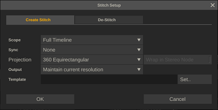
Scope
Determine if SCRATCH processes all slots on the timeline or only the current selected. SCRATCH Creates a new Stitch node for each slot and adds all the source shots in that slot as inputs to the new Stitch node. In case the shot in the slot is already a Stitch node, SCRATCH will skip it.
Sync
Option where SCRATCH will compare the timecodes of all source shots and set a frame offset with the source input nodes to the stitch nodes to synchronize them.
Output
The default resolution of the new Stitch node is the same as the resolution of the Main Output of the Construct. This option allows you to adjust the resolution of the main output and as such the resolution of the new Stitch node.
Template
Load and apply a template that contains positional data for the stitch. This template can be a standard SCRATCH plug-in template (*.pls) which you saved from an earlier session. Or this can be a third party template: AutoPano (*.pano / *.kava), Hugin or PTStitch (*.pto / *.txt). The template file is applied to each created Stitch node.
De-Stitch
This function will remove the Stitch node and place the source shots in the slot again. Note that all settings or grade on the Stitch node is lost.
STITCH NODE
Once the stitch node has been created, you enter the player to tweak the stitch further if needed.
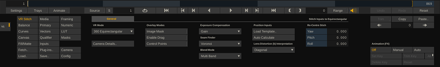
If you did not apply a template when creating the Stitch node, all the source images are presented in a horizontal span. In that case you use either the Auto Calculate option to align the source cameras correctly to crate the equirectangular image or you manually adjust the camera position and settings for the stitch. Use the Camera Details button in the Stitch node menu controls to open the Camera Details panel.
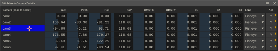
In the panel you can view and adjust the various camera settings:
- Yaw, pitch, roll position in the equirectangular image.
- Field of View of the camera.
- Offset x, y – to adjust the center point of the source camera that is used for lens distortion calculations and transformation into the equirectangular format.
- Lens Distortion parameters (k1, k2, k3)
- Lens Type: Rectilinear or fish eye – which determine how the lens distortion parameters are interpreted.
- Active – toggle to switch a camera include / exclude in the stitched image.
You can multi-select cameras in the Camera Detail panel by ctrl+click
the camera name. When multiple cameras are selected, any change in the
camera parameters is applied to all the selected cameras.
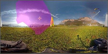
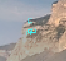
Furthermore, if you hoover the mouse pointer over the column with the camera names the labels will light up in a specific color. If you have the Image Mask option in the stitch node menu enabled, you will also see the image section of that source camera light up in the equirectangular image. Vice versa, if you hoover over the image in the View Port, the corresponding label in the Camera Details panel will highlight. This way you can easily locate a specific camera.
AUTO CALCULATE
The Auto Calculate option attempts to align the source images by finding and matching control points in the source images. Depending on the number of source cameras this process might take some time. The results also depend on the number and quality of the control points the process can detect in the source images.
- If the Auto Calculate does not render good results, you might want to try scrubbing to a different frame which might contain more (usable) control points.
- You can set the base image the Auto Calculate will work from by selecting that camera in the Camera Details Panel. Normally you would select the front camera in your 360 view and set that to the center of the stitch image with the correct rotation – using the yaw, pitch and roll of that camera.
- When you used the Auto Calculate you can view the found control points by enabling the Control Points option in the Stitch node menu. This can help by further manually tweaking a stitch.
OVERLAY MODES
- Image Masks: highlight the source cameras when hovering over the stitched image.
- Enable Drag: when enabled you can click and drag the stitched image in the Viewport to re-center it.
- Control Points: show the control points found after using the Auto Calculate. Note that the control points themselves are not saved in the database but rather the resulting positional data.
EXPOSURE COMPENSATION
SCRATCH tries to detect and compensate for the difference in exposure between the source images.
Please note that, next to automated compensation, you can also apply any grade on the source images directly to improve the stitched result.
SEAM FINDER
This sets the algorithm used to determine the optimal seam in the overlapping source images. Without seam finding SCRATCH will just blend the full overlap. The Adaptive variant of the seam finder causes SCRATCH to re-calculate the optimal seam for each frame again, rather than once for all frames of the shot. If your scene has a lot of motion in it then using the adaptive variant might improve the overall stitch – even though this variant has an impact on performance.
BLEND MODE
The blend mode determines how the overlap / seams of the cameras are blended together.
LOAD TEMPLATES
Load a SCRATCH or third party template file / pano-file with the stitch parameters. This is the same as loading a template when creating the Stitch node. Also note that the generic Load and Save functions in the Matrix allow you to load a SCRATCH or third party template or create a new SCRATCH plug-in template.
LENS DISTORTION INTERPRETATION
Various third party templates have different ways of how they store and interpret the values of the lens distortion of a camera. SCRATCH recognizes the template source and how to interpret the values. This setting shows the interpretation.
RE-CENTRE
With the Yaw, Pitch and Roll you re-center the stitched image to ensure that the front view is in the center of the equirectangular image. Rather than adjust the individual controls you can also use the Enable Drag overlay mode; when enabled you can click and drag the image in the Viewport to re-center.
MASKING CAMERAS
The stitch function by default uses all of the source inputs to find overlap, determine a seam and stitches the images together. However, often you want limit the amount of overlap between cameras to influence the position of the seam. If e.g. an object close to the 360 camera is in multiple sources at the same time, you might want to mask out that object in certain cameras to ensure that the stitch does not run across that object.
You can mask out sections of a source camera simply by creating a full frame layer on the source image of a specific camera and then use the mask option in the Matrix to draw a shape around the object to exclude it from the stitch. You can also track and animate the position of the mask over the length of the shot.
RENDER / CACHE
Stitching does require substantial processing resources: reading and decoding all the input streams + calculating and rendering the equirectangular image. Please note that as with any plug-in in SCRATCH you can cache it to increase playback performance. Please see the details on this in Chapter 5 – The Player in the paragraph on processing and caching media.
VR TRANSFORMER
Transform its input from one 360 format into another. The following conversions are available:
- Cubic -> Equirectangular
- Equirectangular -> Cubic
- Cubic Packed -> Equirectangular
- Equirectangular -> Cubic Packed
- Cubic Packed Stereo -> Equirectangular Stereo
- Equirectangular Stereo -> Cubic Packed Stereo
In the Cubic format the 6 faces of the cube are stored as:
-- | top | -- | --
left | front | right | back
-- | bottom | -- | --
In the Cubic Packed the 6 faces are stored as:
right | left | top
bottom | front | back
The Stereo variants of Cubic Packed and Equirectangular both assume an over/under pattern.
Note that when you convert from one format to the other the aspect of the shot might change. You need to set the actual resolution of the new node yourself. The transformation automatically adjusts itself to a resolution change.
2D - EQ COMP
This plug-in is used to composite a 2D element into an equirectangular image: first place the 2D element as a fill on a layer. Next, insert the plug-in in between to convert the 2D element to equirectangular and position it properly into the 360 scene.
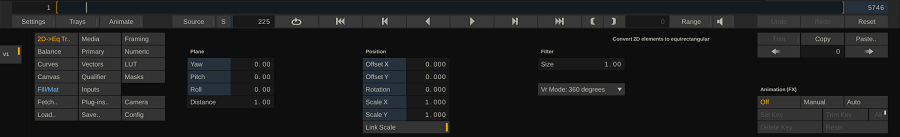
To understand the workings of the effect you should imagine the 2D element being placed on a plane that is about to be wrapped around a sphere.
The Position controls determine how and where the 2D element
is put on that plane. In general, you want to center the 2D element on the plane
as much as possible and use the Position parameters for final tweaking
the 360 scene.
The Plane controls - Yaw, Pitch and Roll - specify the position of that plane relative to the sphere, with the Distance control determining the distance between the sphere center and the plane (default 1.0, meaning the sphere intersecting the plane in the center point).
Finally, the Filter option can help to counter any (anti-aliasing) artifacts that might be caused by the spherical projection.
EQ - 2D EXPORT
This plug-in node can create a 2D version of a 360 shot or timeline. Typically you would insert it into the output tree, followed by a file writer plug-in. Is is available in the Add Output list of the Output menu in the Construct.
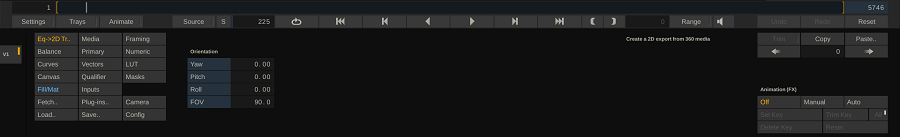
The plug-in has the standard Yaw, Pitch and Roll controls to determine the 2D view inside the 360 projection. You can also set the Field Of View (FOV). To create a full 2D version over a whole shot or timeline you would likely animate these parameters using the regular Animation options to pan through the full movie and make sue the view is always at the correct point of interest.