GENERAL
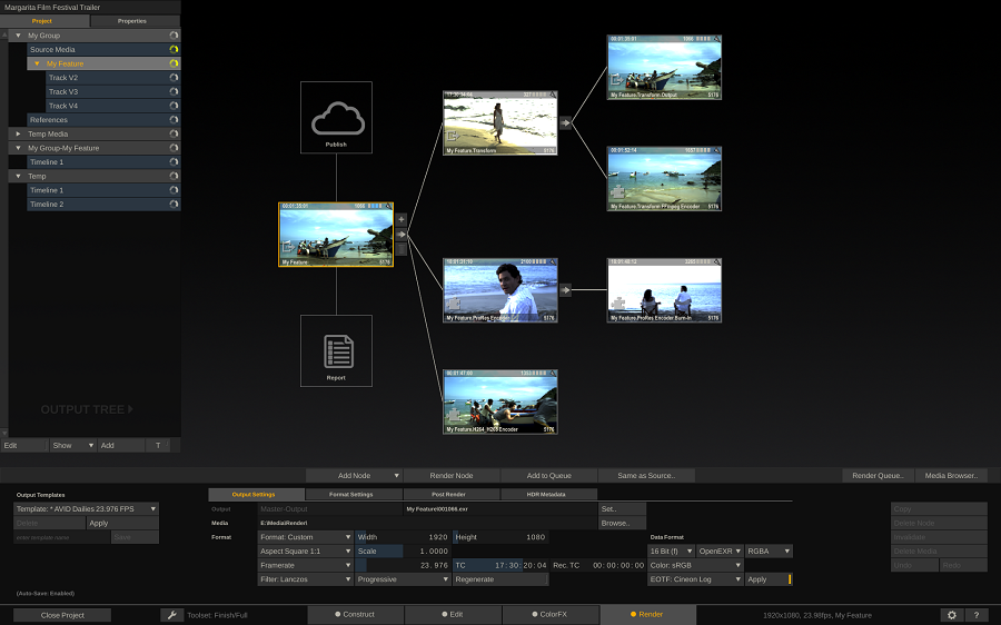
When you select the Outputs button on the main toolbar - all the Slots and Shots of the Construct in the Viewport are replaced with the Pipeline view. That view contains all the output nodes of the Construct. By default there is one (main) Output Node. The left most icon represents the Timeline of the Construct. You can add additional Output Nodes to e.g. render out different formats of the Timeline. The created Pipeline can efficiently process all output versions and formats at once - where each node can serve as input for any number of underlying outputs.
Tip: You can adjust certain settings of an Output Node quickly by dragging and dropping a Clip Node onto it; the Format, Aspect, Framerate and Scale of the Output Node will be updated with those of the shot that was dropped.
MANAGE OUTPUTS
The section on the far left of the menu allows you to add, remove or copy output nodes.
ADD OUTPUT
This button will add a new child Output Node 'after' the current selected node. Clicking the button will show a list of available output formats. The first item 'Image Files' is a collection of formats - the specific sub-format is set elsewhere in the menu after adding the node. The Image Files format is a special type of node in that it also has framing and scaling options in it, plus the option to convert color space (discussed later in this chapter). The second item is the Burn-In: with this node you can add text-overlays to your shot. The last item in the list is the Stereo Generator which can render out a specific stereo pattern. The rest of the list are specific output format plug-ins such as QuickTime, H264 and MXF.
It is recommended that you always add new (derived) output nodes 'after' the main output node.
DELETE
The button will remove the current selected output node and all the child nodes after it. The main Output Node and the icon representing the Timeline cannot be removed.
Note: Removing an Output Node will not automatically remove any generated media of the node from disk. To remove the media, you could use the Delete Media button, discussed in the previous paragraph, before removing the node.
COPY / CREATE VERSION
Copy the selected node. Use the Paste option in the regular Construct view to add the copy to your Construct. Note that you can not copy the Main Output node. If the current selected output node has been rendered, this button will read Create Version. In that case SCRATCH will create a copy of the node and link the rendered media to that copy while un-linking it from the selected output node. The new copy is attached to the pen and can be dropped in any Construct.
MANAGE TEMPLATES
Rather than adding output nodes one by one for each Construct, you can also create and use templates that can store a complete branch of output nodes.
APPLY TEMPLATE
You apply a template by first selecting the Output Node
under which you want the new node/branch of nodes to be created. Next,
select the appropriate Template from the option list and then press the Apply button.
Tip: Always
check the settings of all of the newly created Output nodes; names and
destination folders might have been changed from the template defaults
to ensure uniqueness.
SAVE TEMPLATE
Next to the Save button is a text slate where you can enter a name for the template. The template saves the full branch 'after' but not including(!) the current selected node. Unless the selected node is the last in the branch. In that case only the selected node is included in the template. The name of the Template is added to the Template option list.
Note: When you save a template and have not explicitly set the values of all properties of an output, the values in the template will remain undefined. When loading the template these properties will inherit the values of the parent/preceding node; e.g. if Format is not explicitly set before saving an output node as a template, then the newly created Output node from a loaded template will inherit the Format from the preceding Output node.
DELETE TEMPLATE
This button will remove the current selected item from the Template option list.
OUTPUT NODE
The middle section of the Outputs menu contains various tabs with controls that apply to the currently selected output node. The first tab contains a number of generic settings that are available for all nodes. The Formats Settings and possible subsequent tabs vary depending on the exact type of the Output node; e.g. a QuickTime output requires you to select a specific codec for rendering the media. The Post Render tab allows you to specify an external program or script to be started after the rendering of the node completes. Finally, in the HDR Metadata tab you can generate and specify HDR metadata that is to be included in the rendered media or in sidecar file / report.
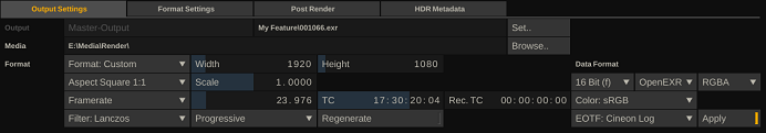
OUTPUT SETTINGS TAB
In case an output node has been processed, the controls will be disabled to prevent accidental overriding of output files or changing only part of an output stream. In order to change the settings of an output node that has been processed, you first have to explicitly invalidate it or delete the underlying media.
NODE NAME
The first Text Slate of the settings panel contains the name of the Output Node. You can change the name of any derived output. The name of default Main output is fixed and is the same as the name of the Construct. A new Output Node will inherit the name of its preceding(parent) Output Node in the Pipeline with a .Output post fix. For example, if the main output is called 'MyConstruct', a derived output from that will be called 'MyConstruct.Output'. This could be renamed to e.g. 'MyConstruct.HD' and any derived node from that will be default named 'MyConstruct.HD.Output'.If the name is not unique within the Construct, an increment is added at the end of the name to ensure that the name is indeed unique. The name of the node is, next to easy identification, used in setting the default for the location and name of processed output files.
FILENAME
The Filename Text Slate to the right of the Output Name has some special functionality. When you click the Set button next to it or on the text slate itself, a new dialog opens up where you can create a filename mask how frames will be processed out of SCRATCH.
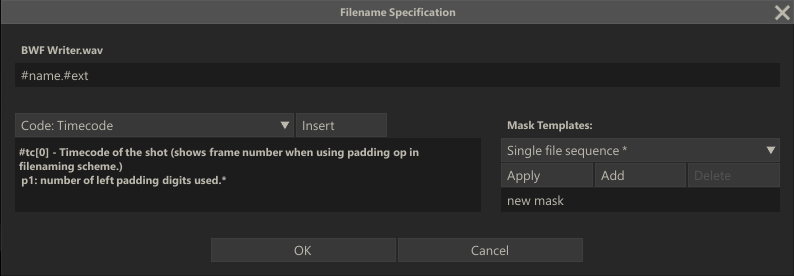
File-Mask
This dialog enables you to create a file mask, using various metadata of the underlying media and timeline, such as #sname (name of the source shot), #event no (slot number) and #frame (frame number). The second line of the dialog shows the actual file mask while the top line shows the actual translation from the current mask, based on the current frame of the Output node. The Code option list provides all the codes that can be used in the file mask. When a code is selected, a description of it and any of its parameters are displayed in the label below the list. With the Insert button you can add the code to the file mask at the position of the text cursor. By adding one or more backslashes '\' you can spread the output over separate sub-folders.
The list below displays all available codes, all of which are also available with the Burn-In plug for text overlays (discussed in more detail in Chapter 9 - PROCESS AND PLUG-INS). In fact some codes are only available as text overlays as they do not fit in a file naming scheme (e.g. an annotation). Those that are available as text overlay are marker with [T]. Some codes have one or two additional parameters. The parameters are explained in the lines below the codes, annotated with 'P1:'. The examples below the list show the usage of parameters.
- #reelid[n,m] - Reel ID of the input.
- p1: skip the first n characters
- p2: max number of characters (0 = all)
- #scene - Scene name of the shot.
- #take - Take name of the shot.
- #name[n,m] - Name of the shot.
- p1: skip the first n characters
- p2: max number of characters (0 = all)
- #sname - Name of the source shot.
- #uuid - Global Unique Identifier of the shot
- #suuid - GUID of the source shot.
- #file - Filename of the shot (excluding extension).
- #sfile - Filename of the source shot (excluding extension). Use #sfile[1] to preserve sequence digits in the original name.
- #note - Annotation stored with the shot. [T]
- #snote - Annotation stored with the source shot. [T]
- #tc[0] - Timecode of the shot.
- p1: number of left padding digits used.
- #stc[0] - Timecode of the source shot.
- p1: number of left padding digits used.
- #rtc - Record timecode.
- #frame[6,0] - Frame number of the shot.
- p1: number of left padding digits used.
- p2: frame number offset used.
- #sframe[6,0] - Frame number of the source shot.
- p1: number of left padding digits used.
- p2: frame number offset used.
- #seq_frame[1] - The current frame even/odd selection.
- p1: 1 returns single character 'L' / 'R', 2 returns 'Left' / 'Right'.
- #eventno[3,1] - The source event/shot number.
- p1: number of left padding digits used.
- p2: event number offset used.
- #eventpos[6,1] - Frame position within the slot of the shot-frame.
- p1: number of left padding digits used.
- p2: frame position offset used.
- #date[ymd] - The current system date. [T]
- p1: y-year m-month d-day number.
- #slotname - Name of the slot.
- #spath - Path of the source shot excluding media folder or drive letter but including last folder separator.
- #fps - The frame rate of the shot in frames per second.
- #res - Resolution of the output eg. 1920x1080.
- #ext - The default filename extension for the output format.
- #project - Name of the project in which the output resides.
- #group - Name of the group in which the output resides.
- #Construct - Name of the Construct in which the output resides.
- #md[a] - Shot Metadata description.
- p1: a valid metadata item code.
- #pmd[a] - Project Metadata description.
- p1: a valid metadata item code.
- #subtitle - The subtitle at the current time. [T]
- #colorspace - Color space of the shot (sRGB, REC709, etc.).
- #srclut - Source Mapping LUT used.
- #gradelut - Grading LUT used (primaries)
- #soundroll - Sound Roll of the shot linked audio.
- #audiotc - Audio timecode of the shot
- #audiofile[c] - Audio file linked to the shot (or underlying input shot)
- p1: the audio channel number (optional).
Below are a number of examples of file-masks using some of the codes from the list, together with the translated actual filename. For these examples we assume that the first shot on the timeline is named 'ShotX' and has reelID 'ABC'.
- myName#frame.#ext -> myName000001.dpx
- myName#frame[3,2] -> myName002.dpx
- #reelid_#sname_#frame.#ext -> ABC_ShotX_000001.dpx
- myFolder\sub#eventno\img#frame.#ext -> myFolder\sub001\img000001.dpx
The first example shows that you can use any text of your own in the file mask alongside the hash tags. The second example shows the use of parameters. In the full list of codes the default values for each parameter is shown. Only when you need to use a different value you add the parameter values to the file mask. The third example shows that you can combine multiple codes in the file mask; there is no practical limit to the number of codes used. The final example shows the use of multiple sub-folders in the file mask. For sub-folders you can also use any of the available codes. Remember that the sub-folder path and filename is in the end added to the render path set for the Output node.So the final example might in the end become D:\Media\Render\myFolder\sub001\img000001.dpx.
Note: If a code does not have a value, e.g. not all slots have a name and you are using #slotname as code, this will translate to an empty string and might lead to error in the final rendering of the output.
Templates
The right half of the dialog allows for saving and loading of file masks as templates. After creating a file mask you can enter a name in the New Template text slate and click on the Add button. The current file mask is then stored with that name in the FileMasks.cfg file in the C:\ProgramData\Assimilator\Settings folder. All templates are listed in the option list above the Apply button. Selecting a template and clicking on Apply will load the corresponding file mask in the top text slate. Use the Delete button to remove a template from the list.
SCRATCH provides three default templates which are always present, cannot be removed nor stored in the FileMask.cfg. These templates are marked with an asterisk (*) in the Template list.
- Single file sequence » all rendered files are numbered based on the consecutive frame number.
- Separate folders » all rendered files are numbered based on the consecutive frame number, but grouped in folder per Slot.
- Folders and shotname + TC » rendered files are grouped in a folder per Slot with the filename containing the original Shot name and the timeline time-code.
Tip: You can load one of the default templates, customize that file mask by adding additional codes/characters and save that again as your own template.
Validation
After you entered a file mask and clicked on the Ok button, SCRATCH will check if the mask might result in duplicate filenames in the render. If that is the case a warning is displayed. For long renders the validation might take a couple of moments to complete.
MEDIA DESTINATION
The large text slate below the output name shows the destination path for images processed from the Output Node. By default, this path is the project’s render directory followed by the name of the Output Node. If the resolution of the output differs from the project's resolution, the resolution is also added to the folder name. If that is not a unique path, an increment is added at the end of the path to ensure that the path is indeed unique.
The BROWSE button to the right of the text slate can be used to open a SCRATCH Browser where you can navigate to a new location for processed images.
Note: Once images have been processed into the destination folder, the BROWSE button changes to DELETE ALL. At this point, the destination path cannot be altered without first deleting any previously processed images. This is a safety mechanism to ensure that SCRATCH can properly track processed images and will not accidentally overwrite important data.
MEDIA FORMAT
The Format pull-down operates in the same way as the Format button in the Project Settings Menu of the Startup Screen. This sets the working resolution for the Output Node. The values for the pull-down are read from the Image Formats.cfg file.
WIDTH
This Numerical Slate defines the horizontal working resolution of the selected Output Node in pixels.
HEIGHT
This Numerical Slate defines the vertical working resolution of the selected Output Node in pixels.
ASPECT
This pull-down determines the aspect ratio to be used for the selected Output Node. The values for the pull-down are read from the Aspects.cfg file.
Note: For details on setting proper aspect ratios and using the Scale parameter, see Chapter 3 - PROJECT SETTINGS MENU.
SCALE
The Scale is a manual control for custom aspect ratios.
FRAMERATE
This pull-down determines the frame rate for the selected Output Node. A specific number can also be entered directly into the Numerical Slate. Next to the pull-down.
TIMECODE
The value set here is used as the starting timecode for the first
frame of the selected Output Node. This is the timecode that will be
written into the header of DPX files when the node is processed. By
default the Output Node inherits the timecode from its inputs.
FILTER
The Filter pull-down determines what type of filtering will be used
when processing the Output Node. This filter is used for any scaling,
translation or rotation operations that are made as part of the shot
framing within the Process menu. For more information on shot framing,
see Chapter 9 – PROCESS AND PLUG-INS.
The type of filtering determines how a pixel’s value is
altered,depending on the pixels surrounding it as the image is
transformed. The range of the filter is derived from the amount of
scaling applied to the image, except in Linear filtering where the
filter size is constant.
SCRATCH filtering falls into three main groups:
Linear-type Filters
Linear filters use a constant slope value for the falloff within the
filter range. These include: Linear, Box and Triangle filtering. The
Linear filter can in general be done in real time by most graphics cards
easily.
Cubic-type Filters
Cubic filters use a standard cubic curve for the falloff within the
filter range. These include: Cubic, Gaussian, Quadric and B-Spline.
Cubic filters create generally softer results.
FIR-type Filters
Some filters use a method that is similar to a FIR, or Finite Impulse
Response, filter in that they use a modified bell-shaped curve for the
falloff within the filter range. Since the values for these curves can
become negative, they have a sharper overall effect than the Cubic
filters. These include; Sinc, Mitchell and Lanczos.
By default the Main Output node uses a Linear filter and any additional created (derived) Output nodes a Lanczos filter.
SCAN MODE
The Scan Mode determines whether the processed frames are Progressive or Interlaced.
- Progressive: These image files are intended to be viewed
on a progressive display system, where each line is drawn in order from
the top of the image to the bottom.
- Interlace F1:These image files are intended to be viewed
on an interlaced display system, where all the odd numbered lines are
drawn first, followed by the even numbered lines.
- Interlace F2: The image files are intended to be viewed
on an interlaced display system, where all the even numbered lines are
drawn first, followed by the odd numbered lines.
Note: Once
images have been processed into the destination folder, the buttons
controlling the output format will be grayed out. This is to ensure that
all images are processed with the same settings throughout the
Construct. To modify any of these values, the processed media must be
removed using the DELETE ALL button.
REGENERATE
This option will, when set, generate new timecode on output/processing rather than passing through the input time code.
RECORD TIMECODE
The Record Timecode can only be set for the Main Output Node of a
Construct and determines the start time of the Timeline. The Record
Timecode is displayed in the Player, showing the timeline position, and
is (optionally) passed to the VCR in a Play-Out session. By default the
timecode starts at zero.
DATA FORMAT
This pull-down allows you to set the bit depth that is used for the output files. The options are:
- 8 Bit: File formats using 8-bit values per color channel
- 10 Bit: File formats using 10-bit values per color channel
- 16 Bit (i): File formats using 16-bit integer values per color channel
- 32 Bit (f): File formats using 32-bit floating-point values per color channel
FILE FORMAT
The Image File Output node can render different formats. Note that when you selected a specialized output node (like a QuickTime or H264 node), this option is not available.
- DPX - The DPX file format is a real time optimized format that includes a file header, which stores metadata such as timecode, keycode, and other information about the file. DPX files typically use 10-bit values per color channel, but can also include 16-bit values.
- Cineon - The Cineon file format is virtually identical to the DPX format except that it does not include a file header.
- Tiff - The TIFF file format is widely used in animation and VFX applications. The TIFF file specification is quite broad and files can be formatted in a variety of ways, which may or may not be real-time playable.
- JPEG - JPEG files are a compressed format that requires CPU processing in order for the files to be decoded into a format that SCRATCH can use. As a result, JPEG files may not be capable of real-time playback.
- OpenEXR - OpenEXR is a common file format for saving multi-channel images. SCRATCH currently only reads the default image channel from OpenEXR. On export SCRATCH by default only adds the timecode and reel-id as meta data. You can however specify in the Advanced System Settings to include all (extended) meta data in the EXR files.
- Targa - The Targa file format is also widely used in animation and VFX applications. Targa files may not play back in real time.
- SGI - The SGI file format is still used by many 3D animation facilities. The SGI format is generally not a real time playable format due to the byte ordering of the files.
- JPEG 2000 - The JPEG2000 file format is used for DCI deliverables. It is a compressed format that requires CPU processing in order for the files to be decoded into a format SCRATCH can use. Please see Chapter 11 - Customization, paragraph 8 for more information on DCI compliance and restrictions.
-
PNG - The PNG file format can be rendered out in 8 and 16 bit.
RGB - RGBA CHANNEL SELECTION
This button allows you to include or exclude the alpha channel in the output file. This is only available if the selected file format supports an alpha channel.
COLOR SPACE/ APPLY
Every node in SCRATCH has an associated color space: Lin/SRGB, Log/Film, Rec709, Rec2020, XYZ (DCI), ACES, Wide Gamut, Scene Linear, P3 (DCI), AdobeRGB. This setting is used to determine the conversion to a specific output device or file. Setting a color space for an output node does not automatically imply conversion of input media to that color space; it just flags the output node as being in that color space which is used when the node is viewed or rendered to file. Only when you enable the APPLY setting next to the Color Space option, SCRATCH will do an automatically conversion of the input media to the color space set on the output if the two are not the same.
The other case in which SCRATCH will do an automatic color space conversion is when the color space of the node being viewed and colorspace of the monitor(s) as set in the Player are different. Please see for more information on the Monitor settings in Chapter 5 - The Player.
Note that each color space has its own associated gamma value / curve that will be used with a conversion from one space to the next. The default gamma for each of the available color spaces can be adjusted in the project settings in the startup module.
SDR / HDR
This pull-down determines which Electo Optical Transfer Function (EOTF) is / should be associated with the media. There are 3 possible values:
- SDR - Standard Dynamic Range
- PQ - Perceptual Quantizer (SMPTE ST-2084)
- HLG - Hybrid Log-Gamma
The associated EOTF function is also taken into account with possible (color and gamma space) conversions when using the Apply button (see above).
FORMAT SETTINGS - TAB(S)
Depending on the type of output node - the Output view might display additional tabs with various settings. The different node types and node specific settings are discussed in more detail in Chapter 9 – PROCESS AND PLUG-INS.
POST RENDER TAB
In the Post Render tab you can select an external script or program that SCRATCH should execute after the rendering of an output node has completed. The first step to set this up is to create a so called Post Render - Custom Command. In the System Settings - Preferences dialog you can create Custom Commands which are available with all projects on the system. Chapter 11 - CUSTOMIZATION discusses in detail on how to create a (Post Render) Custom Commands. Once you created one or more Post Render - Custom Commands you can select them from the option list in the Post Render tab of the Output menu.
Please note that Appendix B - Database, XML, XSLT and HTML contains a number of sample files for scripting that also includes a Python script that can be used as a Post Render Command. The sample script is intended to be used with the MXF AMT Export node. This specific output node uses the AVID AMT library to render out MXF. Although you can set a naming mask for the output, SCRATCH can only use that for the sub folders of the render - the name of the actual MXF is controlled by the AMT library and it adds a random character sequence to a name to ensure it being unique. This is however not always what your want. The script - when executed after the render - will make a copy of each MXF file to the root of the render folder that you specified and rename the MXF file to the naming mask you specified. Note that you need to make a copy instead of just renaming them as the files are still in use as long as the project is opened (and when the script executes). Appendix B lists the various steps to setup this configuration in more detail.
HDR METADATA TAB
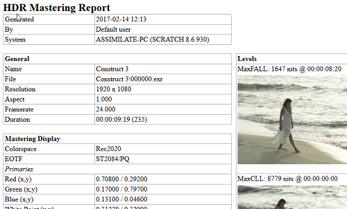
On the HDR Metadata tab you enter the color properties and settings of the reference display you are using with the grading and mastering of your media. This metadata is then either included in the rendered output or included in a side car file which can be used for viewing the finalized media.
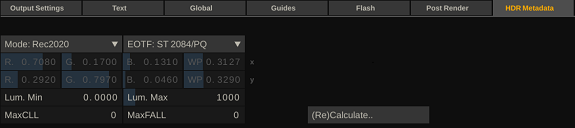
The default value for this metadata are linked to your project default settings. However you can adjust the values for each output node separately. First you select one of the color spaces that are generally associated with HDR and then the Electro Optical Transfer Fucntion (EOTF). Selecting one of the default color spaces will automatically set the RGB primaries for that color space as well as the associated white points. You can also select a custom color space and adjust all the matrix values as needed.
The minimum and maximum luminance settings should be set to those of your reference (HDR) monitor.
The MaxFALL and MaxCLL metadata values depend on the actual (graded) media and should be explicitly calculated before every render of the output node. These values are averages over the full timeline and as such can take time to calculate. When you select the (Re)Calculate button, SCRATCH will add a process queue item for this to be calculated in the background. The Process Queue is discussed in more detail later in this chapter.
When the Process Queue item finishes the recalculation, SCRATCH will also generate an HDR report. this report contains all the static metadata, the MaxCLL and MaxFall dynamic metadata, media positions and proxy images of the those frames.
PROCESSING OUTPUT NODES
Once you have setup your Output Nodes, you can start processing them. All processing is done through the Process Queue, which will process all nodes as efficiently as possible based on relations between the nodes, the order of adding them to the queue and any schedule for processing you might have set. To manage the Process Queue you can press the corresponding button on the main menu, which will pop up a dialog.Details on that dialog are discussed later in this chapter. In the Output Menu there are a number of buttons for basic processing control.

PROCESS
With this button you add the current selected Output Node to the Process Queue and start to process it. The text on the button will change to Abort. Clicking this button will stop the processing. Furthermore the proxy or icon in the Pipeline view will change; a disk icon is shown on top of the icon or proxy indicating that frames were processed for the node. Also, in case of the proxy view a progress bar in the proxy will show. Last, the proxy will show an image of the output when a number of frames have been processed.
Note: The disk icon will also appear in the Project tree with the current Construct, indicating that a node in the Construct is being processed.
Note: When processing, all the settings controls will be disabled to prevent conflicting settings while processing.
ADD TO QUEUE
This button will add the selected Output Node to the Process Queue but it will not start processing. You can use this function to add multiple nodes to the queue and control/schedule processing from within the Process Queue dialog, discussed in detail later in this chapter.
Note: Adding an Output Node to the Process Queue does NOT make a copy. Any changes made to the node between adding it to the queue and processing it will end up in the final result.
INVALIDATE
Once an Output Node has been processed this button will invalidate the underlying media. This means that the media will not be deleted (for that use the Delete Media button, discussed previously) but if the Node is processed again, the media will be overwritten.